Tubular falling film evaporator

A falling film evaporator, tube-type technology, applied in vertical tube evaporators, evaporation, chemical instruments and methods, etc., can solve the problem of large radial damping of steam and heat exchange tubes, low efficiency of tube-type falling film evaporators, removal The problem of incomplete vapor-liquid separation of the bubbler can be solved, so as to reduce the processing cost, strengthen the rigidity, and facilitate maintenance and replacement.

Inactive Publication Date: 2010-07-21
张培洲 +1
View PDF1 Cites 17 Cited by
  • Summary
  • Abstract
  • Description
  • Claims
  • Application Information

AI Technical Summary

Problems solved by technology

[0005] 1) The existing equipment introduces circulating fluid into it through the liquid inlet pipe installed on the upper part, and then distributes it in each heat exchange tube with a distributor. The heat exchange tubes used in existing heat exchangers must have a certain wall thickness, otherwise it will cause insufficient structural strength, and even pull the heat exchange tubes from the upper and lower tube sheets, which causes the existing tubular falling film The heat exchange efficiency of the evaporator is poor due to the large wall thickness of the heat exchange tube; on the other hand, because the circulating fluid enters from the top of the equipment, its kinetic energy is relatively large, and it will carry a large amount of foam. To overcome this Problems, other technical measures have to be adopted, which will increase the cost of equipment manufacturing and increase the difficulty of manufacturing;
[0006] 2) The efficiency of the existing tubular falling film evaporator is low;
[0007]3) In the existing tube-type falling film evaporator, a separation chamber is directly installed under the lower tube plate, and a demister is directly installed in the separation chamber. Due to the pulling effect of the system vacuum, a large amount of vapor-liquid mixture containing organic pollutants will be quickly brought to the demister for vapor-liquid separation, but due to the high flow rate, short distance, and large flow rate of the vapor-liquid mixture flowing out through the lower tube plate And other characteristics, often cause the vapor-liquid separation of the demister is not complete, so that the steam containing organic pollutants is brought to the next effect evaporator to be condensed as a heat source, which further deteriorates the quality of the secondary condensed water
[0008]4) In the prior art, the steam used as the heating source enters the equipment and directly contacts the heat exchange tubes, which will have a certain degree of impact on the exchange tubes, which will have a certain impact on the equipment. The service life has a certain impact, and at the same time, the radial damping between the steam and the heat exchange tube is relatively large, which is not conducive to heat exchange

Method used


Image

  • Tubular falling film evaporator
  • Tubular falling film evaporator
  • Tubular falling film evaporator

Examples


Embodiment Construction

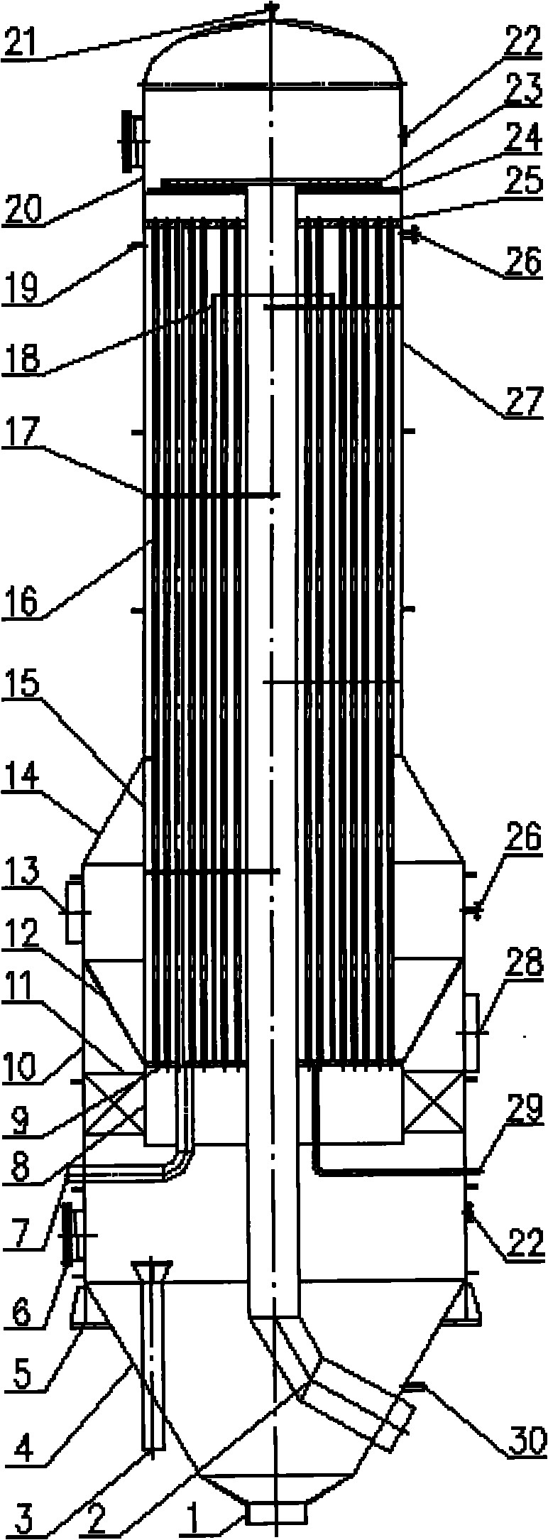
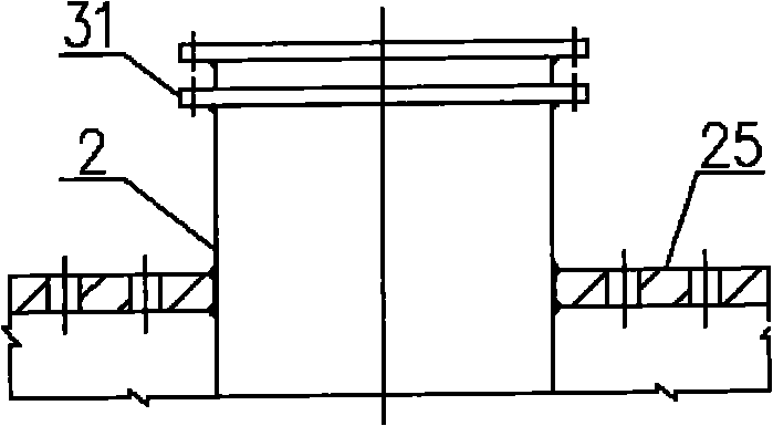
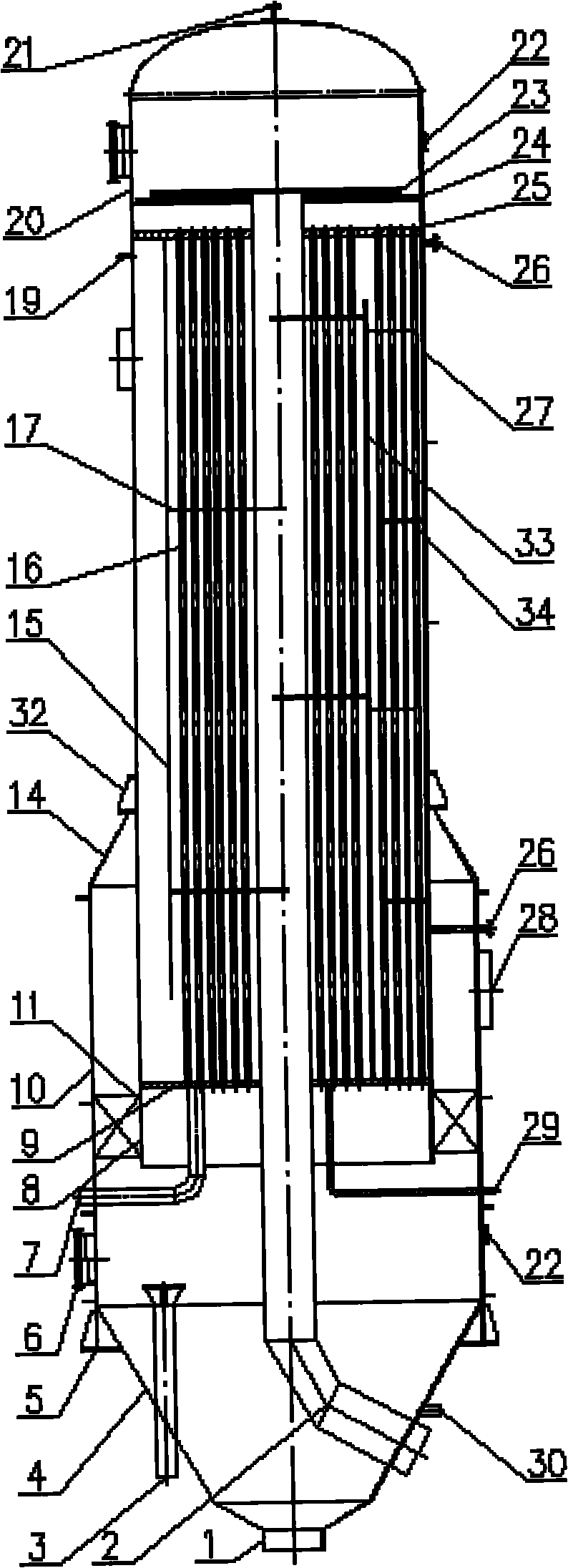
[0027] attached figure 1 In the first embodiment of the present invention given, the blanks of the upper and lower tube plates 25 and 9 are formed by forging, and after heat treatment, they are subjected to machining such as drilling and other processes, and after being erected, they are assembled with the central circulation tube 2 according to the design requirements. Butt welding. The assembly of the upper and lower tube plates 25, 9, the central circulation tube 2, the stripping drum 18, and the heat exchange tubes 16, baffles 17 and other components are assembled into a heat exchange tube bundle. The heat exchange tube bundle and the upper tube box 20, the heat chamber shell 27, the separation chamber shell 10, the cones 12, 14, the separation chamber lower cone 4 and other components are assembled and welded to form the whole equipment. Among them, the nozzles of the heat exchange tubes 16 are tightly connected with the upper and lower tube plates 25 and 9 by expansion ...


PUM


Abstract

The invention relates to a special type heat exchanger, in particular to a tubular evaporator with a stripper unit, which is used for alkali recovery work in papermaking industry. The evaporator of the invention is arranged in the middle in a shell, namely the position of an axis, a central circulating tube of which an inlet is positioned at the lower part is fixed by an upper tube plate and a lower tube plate, the top part thereof is provided with a fluid dispenser, each heat exchange tube is arranged around the central circulating tube, the central circulating tube is fixed with the upper and the lower tube plates in a welding manner, the lower part of the shell is provided with a chamber which is connected with a steam inlet and provided with an expansion section, the lower chamber wall of the chamber with the expansion section is fixed with the lower tube plate, the lower part of the chamber with the expansion section is connected with a separating chamber in which a demister is arranged, and the lower tube plate is provided with a condense sewage outlet.

Description

technical field [0001] The invention relates to a special type of heat exchanger, especially a device for treating sewage to meet environmental protection requirements, such as a tube evaporator used in the paper industry for alkali recovery. The present invention consists of a shell, a heat exchange tube, a liquid distributor, a tube plate, a steam inlet, a demister, a condensed water pipe, a liquid outlet pipe, a liquid inlet pipe, a demister, a secondary steam pipe and a liquid Bit control device configuration. Each heat exchange tube is fixed in the shell with upper and lower tube sheets, and a heating chamber is formed between the upper and lower tube sheets. Baffles are arranged in the heating chamber, and the part below the lower tube sheet forms a vapor-liquid separation chamber. Background technique [0002] Compared with other rising film evaporators, the tubular falling film evaporator has no static pressure effect, and will not cause temperature difference loss....

Claims


Application Information

Patent Timeline
IPC IPC(8): B01D1/06B01D1/22
CPCY02P70/10
Inventor 张培洲邵珲张舒
Owner 张培洲
Why Eureka
Try Eureka