
Direct current voltage regulation-based maximum power point tracking method for photovoltaic array with stable charging circuit

A technology of maximum power tracking and photovoltaic array, which is applied to battery circuit devices, circuit devices, and energy-saving charging equipment, etc., and can solve problems such as extra power loss and unstable methods

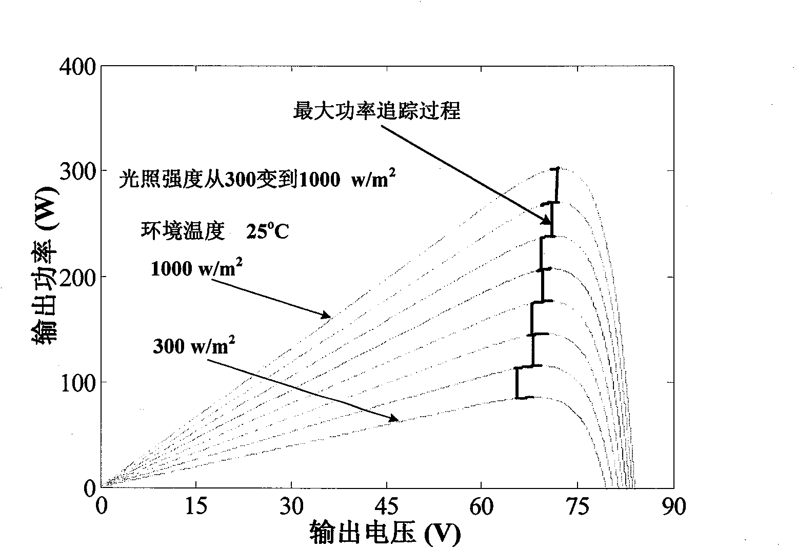
Inactive Publication Date: 2010-07-14
周德佳
View PDF0 Cites 23 Cited by
  • Summary
  • Abstract
  • Description
  • Claims
  • Application Information

AI Technical Summary

Problems solved by technology

[0005] At present, the maximum power tracking technology applied to solar photovoltaic array charging includes atmospheric pressure method, first-order hill climbing method, conductance modulation method, etc. These methods generally require two control loops, one of which is used to control the output voltage or output voltage of the photovoltaic array. Current, another control loop controls the duty cycle of the charging circuit, there must be some interaction between the two control loops, which will cause some additional power loss
Another maximum power tracking method is to directly determine the duty cycle of the BUCK charging circuit according to the change direction of the power emitted by the photovoltaic array. Although this method is simple to control, it is not stable in practical applications and it is difficult to achieve stable operation of the photovoltaic array. at maximum power point

Method used


Image

  • Direct current voltage regulation-based maximum power point tracking method for photovoltaic array with stable charging circuit
  • Direct current voltage regulation-based maximum power point tracking method for photovoltaic array with stable charging circuit
  • Direct current voltage regulation-based maximum power point tracking method for photovoltaic array with stable charging circuit

Examples


Embodiment Construction

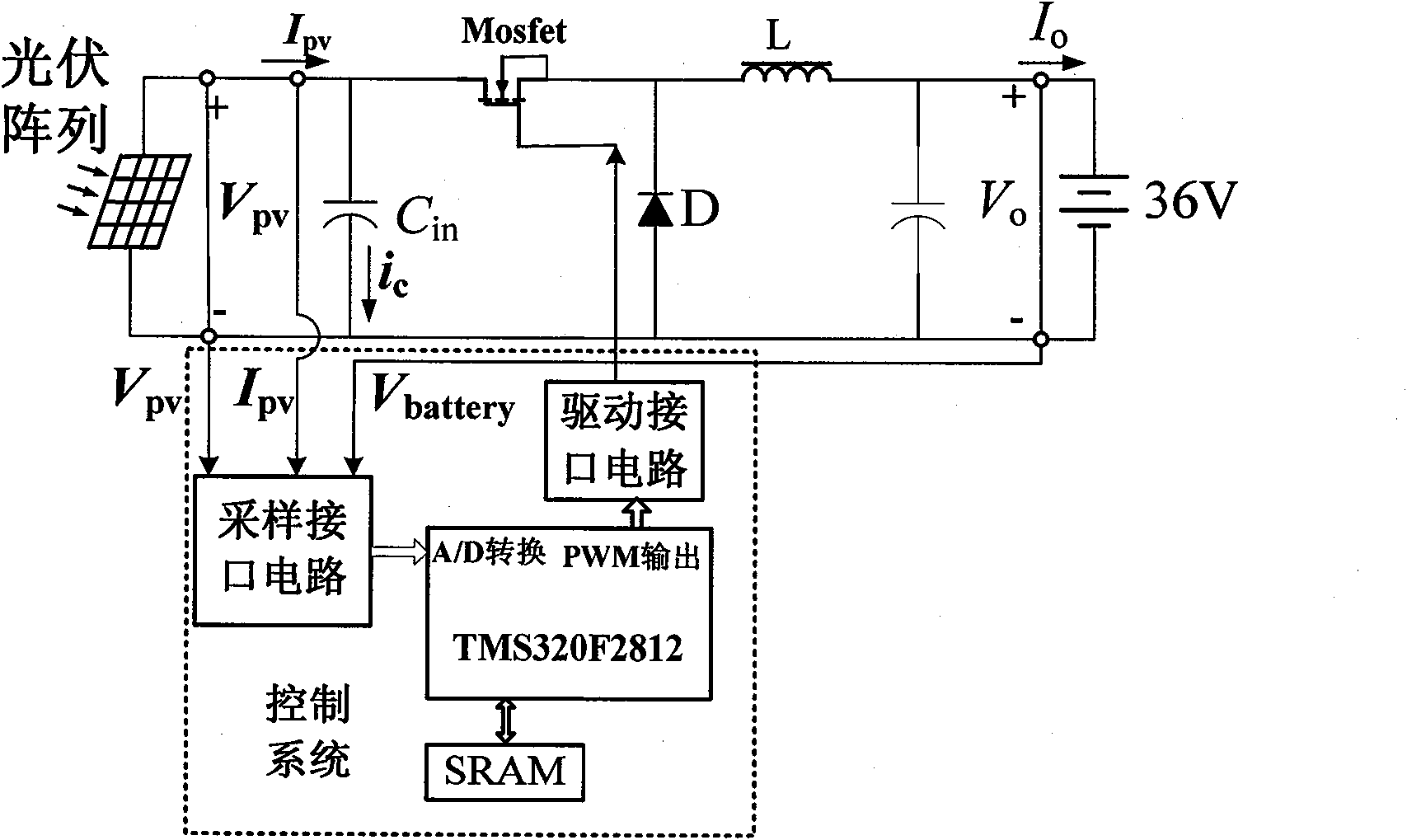
[0025] Such as image 3 As shown, the independent photovoltaic power generation system applying the maximum power point tracking technology described in the present invention includes:

[0026] 1) Solar cell array: The solar cell array is the input of the independent photovoltaic power generation system, which provides electric energy for the whole system. Under daylight conditions, the solar cell converts the received light energy into electrical energy, and charges the battery through the charging circuit; after dark, the solar cell stops working and the output terminal is open.

[0027] 2) DC bus input capacitor: it mainly plays a role of filtering.

[0028] 3) Battery: As the energy storage link of an independent photovoltaic power generation system, the battery converts the electrical energy output by the solar cell into chemical energy and stores it during the day, and then converts it back into electrical energy and outputs it to the load at night. The power supply of...


PUM


Abstract

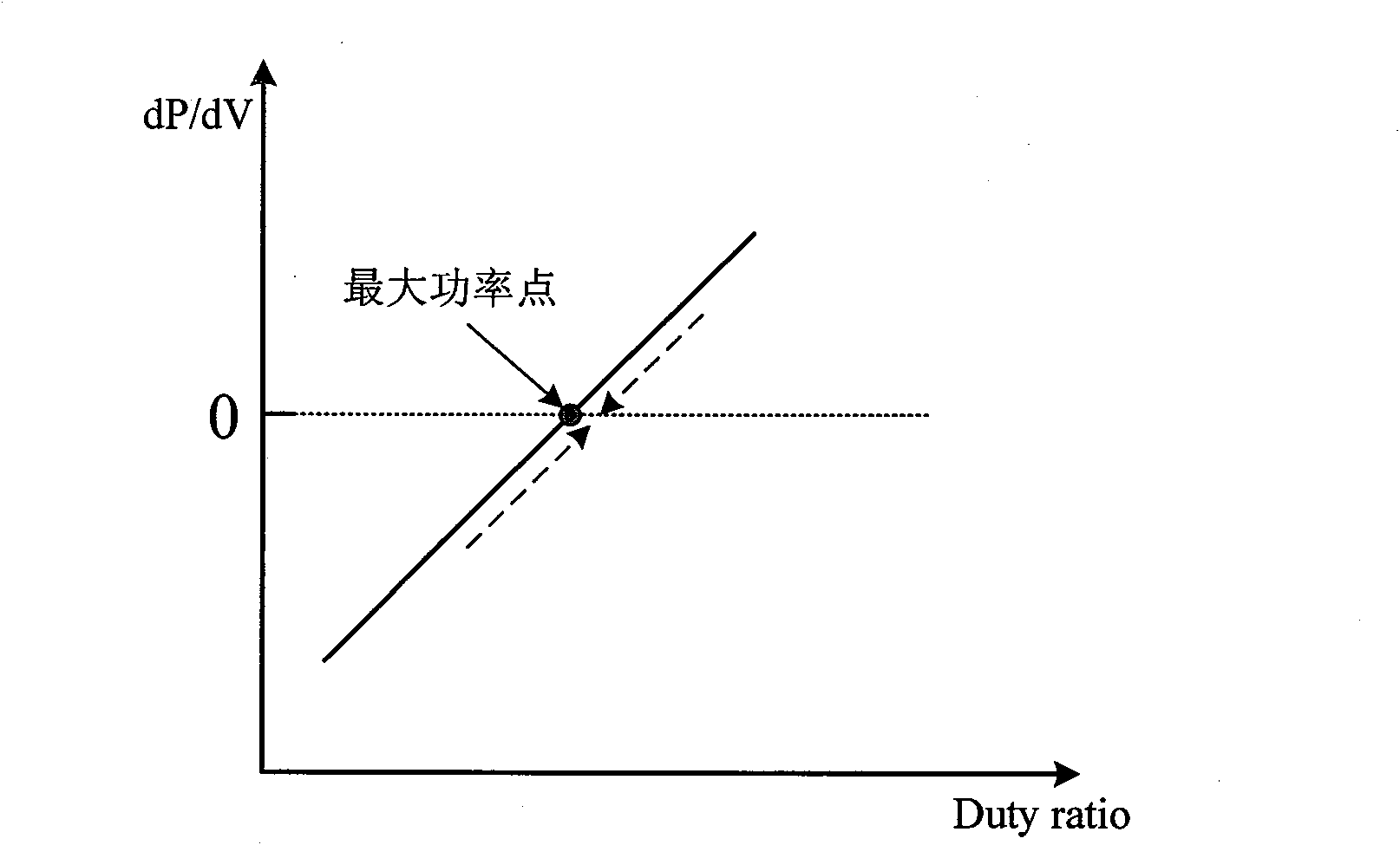
The invention relates to a maximum power point tracking method for an independent photovoltaic power generation system, and belongs to the technical field of photovoltaic power generation. A control system for a Buck circuit to charge a storage battery is utilized by a photovoltaic array, and the duty cycle of an MOSFET switching tube in a Buck charging circuit is directly controlled by utilizing a differential value of power to voltage, so the maximum power output of the photovoltaic array can be maintained under the condition that the luminance and ambient temperature are changed, and the storage battery is quickly charged in an optimization way. The maximum power point tracking method has the advantages of simpleness, directness and effectiveness; when the illumination intensity is suddenly increased or a cloud in the air comes, the method can make the system respond quickly and can timely lock the system to work at the maximum power working point, so energy loss is effectively prevented, the system efficiency is improved, and the system cost is indirectly reduced.

Description

technical field [0001] The invention relates to a photovoltaic charging technology for stably and quickly realizing maximum power tracking of a photovoltaic array, and belongs to the application field of independent photovoltaic power generation system control technology. Background technique [0002] The independent photovoltaic power generation system has its own energy storage link, which can provide continuous power output without being connected to the grid. Therefore, it has been gradually applied in occasions such as high-pressure sodium lamps and LED lamps for battery charging. [0003] The electrical characteristics of solar photovoltaic array output power and voltage, output current and voltage have strong nonlinear characteristics, and its output power is affected by light intensity, ambient temperature and load conditions. Even under the same light intensity and ambient temperature, the output power of different solar photovoltaic arrays is different because of t...

Claims


Application Information

Patent Timeline
IPC IPC(8): H02J7/00G05D3/00
CPCY02E70/40Y02E60/10
Inventor 周德佳
Owner 周德佳
Learn More