Anti-phase microwave power divider with arbitrary power distribution ratio
A technology of microwave power divider and distribution ratio, which is applied in the direction of waveguide devices, electrical components, connecting devices, etc., to achieve the effects of reduced volume, easy implementation, and good phase bandwidth
Inactive Publication Date: 2010-07-14
NANTONG UNIVERSITY
View PDF3 Cites 11 Cited by
- Summary
- Abstract
- Description
- Claims
- Application Information
AI Technical Summary
Problems solved by technology
But so far, researchers still focus on the equal-part inverting power divider designed by balanced transmission line, and the design of inverting microwave power divider with arbitrary power distribution ratio has not been found in the existing literature. See the report
Method used
View moreImage
Smart ImageViewing Examples
Examples
Embodiment
Login to View More PUM
 Abstract
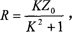
The invention relates to an anti-phase microwave power divider with arbitrary power distribution ratio. The length of a work wave is lambda; the divider has a parallel strip line, wherein the width of two arms of the strip line is as the same as each other, the depth of the strip line is h, and the characteristic impedance is Z0; public metal earth is inserted into a microwave substrate at the h / 2 of the depth of one side of the parallel strip line, wherein the inserting depth is l1; a back-to-back symmetrical micro strip pair with the length of l1 and the same width of the arm is formed; thewidth of the arm corresponding to public earth is changed to form into an asymmetric micro strip pair with the length of lambda / 4 and the different lengths of the two arms; the parallel strip line terminal lead input port with the depth of h and the asymmetric micro strip lead two output ports with the depth of h / 2 respectively have output power of P2 and P3 and arbitrary power distribution ratios of 1: K2, wherein the K2 equals to1, 2, 3... ; and the characteristic impedance corresponding to the asymmetric micro strip pair is respectively as follows: the public earth is provided with a fold line-shaped gap corresponding to the output end, and the symmetric center of the gap is inserted into the isolation resistance, wherein the vertical distance from the isolation resistance to the output port is as the same as the inserting depth. The divider has the advantages that the anti-phase belt width is wide, can design different arm widths of the asymmetric micro strip pair to obtain two powder distributions with arbitrary power ratio, and has good isolation and small power dissipation.
Description
technical field The invention relates to a microwave power divider, in particular to an anti-phase microwave power divider with any power distribution ratio. Background technique A microwave power divider is a multi-port microwave network that divides the input microwave signal power into equal or unequal power outputs, and is widely used in microwave and communication systems. According to the phase difference of the two output ports, the power divider can be divided into a non-phase distribution type and a reverse phase distribution type. In recent decades, many achievements have been made in both theoretical research and design of non-inverting power splitters, among which the Wilkinson power splitter is the most typical. The inverting power divider realizes a balanced / differential circuit, and has a wide and effective application prospect in improving the performance of microwave circuits. In the past, in order to obtain opposite phase characteristics at the two output...
Claims
Login to View More Application Information
Patent Timeline
 Patent Type & Authority Applications(China)
IPC IPC(8): H01P5/16
Inventor 唐慧陈建新周立衡包志华薛泉章国安徐晨
Owner NANTONG UNIVERSITY
Features
- R&D
- Intellectual Property
- Life Sciences
- Materials
- Tech Scout
- Unparalleled Data Quality
- Higher Quality Content
- 60% Fewer Hallucinations
Learn More Browse by: Latest US Patents, China's latest patents, Technical Efficacy Thesaurus, Application Domain, Technology Topic, Popular Technical Reports.
© 2025 PatSnap. All rights reserved.Legal|Privacy policy|Modern Slavery Act Transparency Statement|Sitemap|About US| Contact US: help@patsnap.com


