Oil-return control method of large-head long-piping heat pump air conditioning system

A heat pump air conditioning, oil return control technology, applied in heating mode, heating and ventilation control system, heating and ventilation safety system, etc. Affecting system operation and other problems, achieving the effect of good accuracy, thinning thickness, and ensuring oil return efficiency

Active Publication Date: 2010-07-14
湖南湖大瑞格能源科技有限公司
View PDF4 Cites 12 Cited by
  • Summary
  • Abstract
  • Description
  • Claims
  • Application Information

AI Technical Summary

Problems solved by technology

However, the usual oil return measures cannot guarantee complete oil return, and lubricating oil still accumulates at the bottom of the evaporator and the suction riser, which affects the operation of the system

Method used


Image

  • Oil-return control method of large-head long-piping heat pump air conditioning system
  • Oil-return control method of large-head long-piping heat pump air conditioning system
  • Oil-return control method of large-head long-piping heat pump air conditioning system

Examples


Embodiment 1

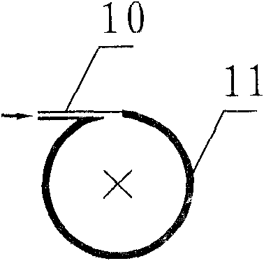
[0029] Embodiment 1: as figure 1 As shown, at the bottom of condenser (outdoor heat exchanger) 3 and evaporator (terminal heat exchanger) 6, and at the bottom of condenser (outdoor heat exchanger) 3 and compressor 1 suction pipe of the heat pump air conditioning system with high drop and long piping By-pass pipes 10 are installed between them; figure 2 , the bypass pipe 10 communicates with the refrigerant pipe 11 at the tangential position of the refrigerant pipe 11 at the bottom of the evaporator 6, and the bypass pipe 10 communicates with the lower part of the suction pipe at the tangential position of the suction pipe of the compressor 1; A solenoid valve 7 is installed on the bypass pipe 10 installed between the bottom of the evaporator 3 and the evaporator 6, the solenoid valve 7 is connected to the controller 9, and a flow sensor 8 is installed in front of the expansion valve 4, and the flow sensor 8 is connected to the refrigerant flow meter 5 , the controller 9 is c...

Embodiment 2

[0043] Embodiment 2: The system composition is the same as that of Embodiment 1, taking a direct expansion ground source heat pump with a cooling capacity of 5kW and a heating capacity of 4.5kW as a specific example. It is 12.7×1mm, and the buried depth is 25 meters. The specific operation steps of the oil return control method are as follows:

[0044] Step S 1 : Under heating conditions with an evaporation temperature of 5°C. The minimum refrigerant flow Gr of the heat pump air-conditioning system is preset to be 65.15Kg / h, and the normal operation time is T 1 2 hours, system oil return running time T 2 is 5 minutes;

[0045] Step S 2 : start up and enter the heating mode;

[0046] Step S 3 : Enter the normal running state and start recording the running time T;

[0047] Step S 4 : continuously monitor the refrigerant flow rate G of the heat pump air conditioning system;

[0048] Step S 5 : Compare the refrigerant flow G of the continuously monitored heat pump air-c...


PUM


Abstract

The invention relates to an oil-return control method of a large-head long-piping heat pump air conditioning system, which is characterized in that a bypass pipe is respectively installed between a condenser and the bottom part of an evaporator and between the condenser and the lower part of a compressor air suction pipe of the large-head long-piping heat pump air conditioning system, wherein the bypass pipe is tangentially connected with the condenser and the compressor air suction pipe; the flow rate of refrigerant inside the pipeline and the running time of the system are instantly monitored, when the flow rate of the refrigerant reaches a given quantity and the running time reaches a given time, the bypass pipe is opened, the high-pressure refrigerant liquid is spayed into a lubricant converging area on the bottom part of the evaporator or on the lower part of the air suction pipe in a tangential direction after being throttled by the bypass pipe, so the accumulated lubricant inside the refrigerant pipe with stoppage is brought back to the compressor so as to realize the successful oil return of the system. Under the condition that the normal work of the heat pump air conditioning system is free from being influenced, the oil return efficiency of the system can be effectively improved, the running stability of the system can be improved, the compressor can be prevented from having malfunction because of the oil shortage, and the high-efficient running of the large-head long-piping heat pump air conditioning system can be ensured.

Description

technical field [0001] The invention relates to heat pump air-conditioning technology, in particular to an oil return control method for a heat pump air-conditioning system with high drop and long piping. Background technique [0002] High drop long piping heat pump air conditioning system is widely used in VRV system, household air conditioning system and direct expansion ground source heat pump system. The heat pump system with high drop and long piping is a primary refrigerant system, and the cooling capacity is directly transferred by the refrigerant piping. Compared with the traditional secondary refrigerant system, this system does not require a huge and bulky supporting system and complicated pipeline design, it is more convenient to install and maintain, and saves a lot of manpower, material resources and installation space; it does not need a dedicated machine room, which can save a lot of space; simple Piping and wiring system, portable indoor / outdoor unit, a smal...

Claims


Application Information

Patent Timeline
Patent Type & Authority Applications(China)
IPC IPC(8): F25B31/00F24F11/00
Inventor 周晋郭永辉王海标李洪强张国强吴加胜
Owner 湖南湖大瑞格能源科技有限公司
Why Eureka
Try Eureka