Clip and support member

A technology of supporting parts and clips, applied in the direction of fasteners, connecting members, threaded fasteners, etc., can solve the problems of dullness of joints and other problems, and achieve the effect of sufficient retention force

Active Publication Date: 2012-09-05
NIFCO INC
View PDF1 Cites 0 Cited by
  • Summary
  • Abstract
  • Description
  • Claims
  • Application Information

AI Technical Summary

Problems solved by technology

[0004] In other words, in order to improve the retaining force of the clip without changing the insertion force of the pin, it is enough to make the widening amount of the claw part and the state of the step close to the maximum widening amount. For this reason, the method of reducing the step is considered, but if the The step, the sense of joint when the claws cooperate with the step becomes dull

Method used


Image

  • Clip and support member
  • Clip and support member
  • Clip and support member

Examples


Embodiment Construction

[0039] Hereinafter, a clip according to an embodiment of the present invention will be described with reference to the drawings.

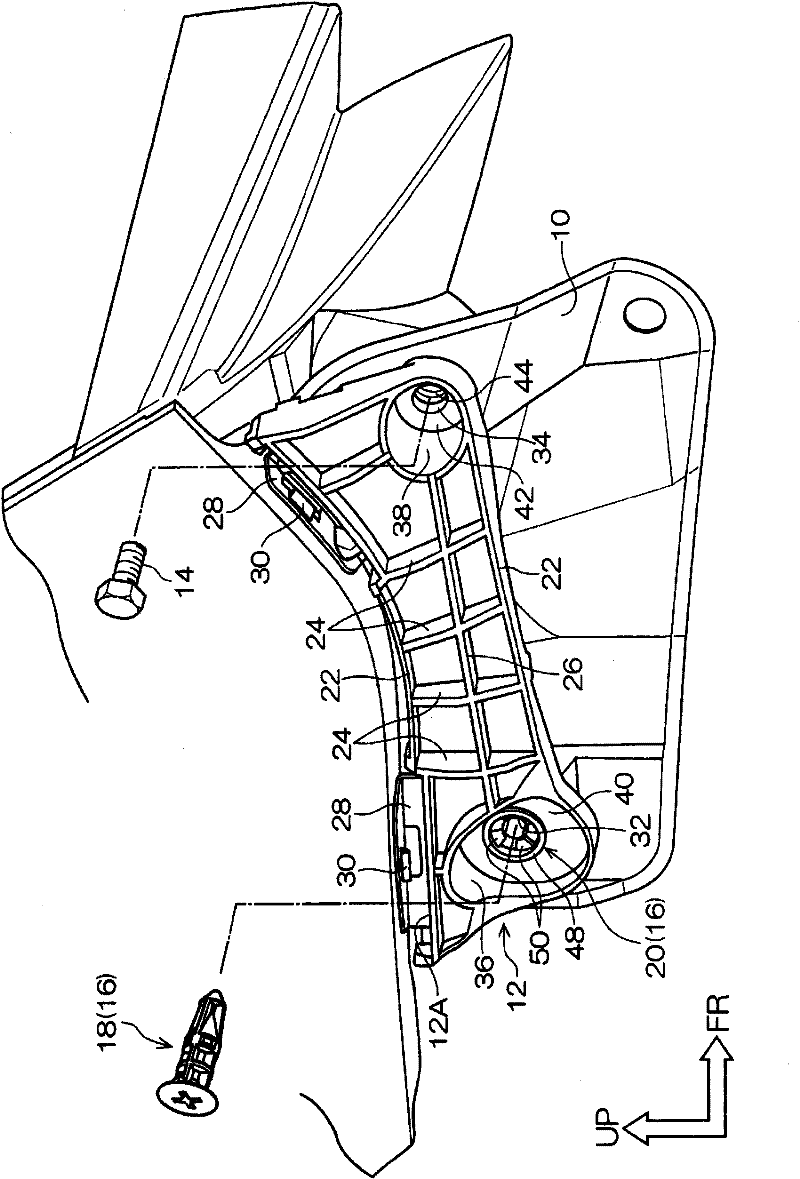
[0040] like figure 1 As shown, in order to install a vehicle bumper (not shown) on the main body panel 10, a retainer (support member) 12 is provided between the main body panel 10 and the bumper, and the bumper is fixed to the bumper by the retainer 12. On the main body panel 10.

[0041]In order to fix the holder 12 to the main body panel 10 , a clip 16 formed of resin different from the fixing screw 14 is used. The clip 16 is composed of a male part 18 and a female part 20 , the female part 20 being provided integrally with the holder 12 here.

[0042] The retainer 12 has a substantially long plate shape and forms a gentle arc along the longitudinal direction so as to follow the shape of the fixing portion of the main body panel 10 . In addition, arrow UP in the figure indicates the upward direction of the vehicle, and arrow FR indicates the ...


PUM


Abstract

Insertion force for mounting a clip (16) into a body panel (10) and holding force for holding the clip (16) after the mounting are obtained by an engagement leg section (52). Click feeling provided when the clip (16) is mounted into the body panel (10) is obtained by a click leg section (54).

Description

technical field [0001] The present invention relates to a clip used when mounting a bumper of a vehicle, etc., and a support member provided with the clip. Background technique [0002] The bumper of the vehicle is fixed to the main body panel by a holder, and the holder is fixed to the main body panel by clips. For example, in Patent Document 1 (Japanese Unexamined Patent Publication No. 2006-125571), the clip is composed of a buckle and a pin, and the bag of the buckle is inserted into the mounting holes respectively formed on the main body panel and the holder. After the main body panel and the retainer are sandwiched between the flange portion and the claw portion formed on the buckle, the pin is inserted into the pocket. Furthermore, by expanding the claw portion from the inside with the pin, the holding force of the retainer to the main body panel is increased only by increasing the amount of expansion of the claw portion. [0003] However, in Patent Document 1, when...

Claims


Application Information

Patent Timeline
Patent Type & Authority Patents(China)
IPC IPC(8): F16B19/10
CPCF16B19/1081F16B2005/0671F16B19/10Y10T24/45262Y10T24/309Y10T24/307
Inventor 西野正明
Owner NIFCO INC
Why Eureka
Try Eureka