fastening element

A technology for fastening elements and ribs, which is applied in the direction of quick action fasteners, building components, connecting components, etc., and can solve problems such as insufficient holding force of fastening elements

Active Publication Date: 2017-03-15
HILTI AG
View PDF6 Cites 0 Cited by
  • Summary
  • Abstract
  • Description
  • Claims
  • Application Information

AI Technical Summary

Problems solved by technology

If the diameter of the opening is chosen too large, the holding force of the fastening element is insufficient

Method used


Image

  • fastening element
  • fastening element
  • fastening element

Examples


Embodiment Construction

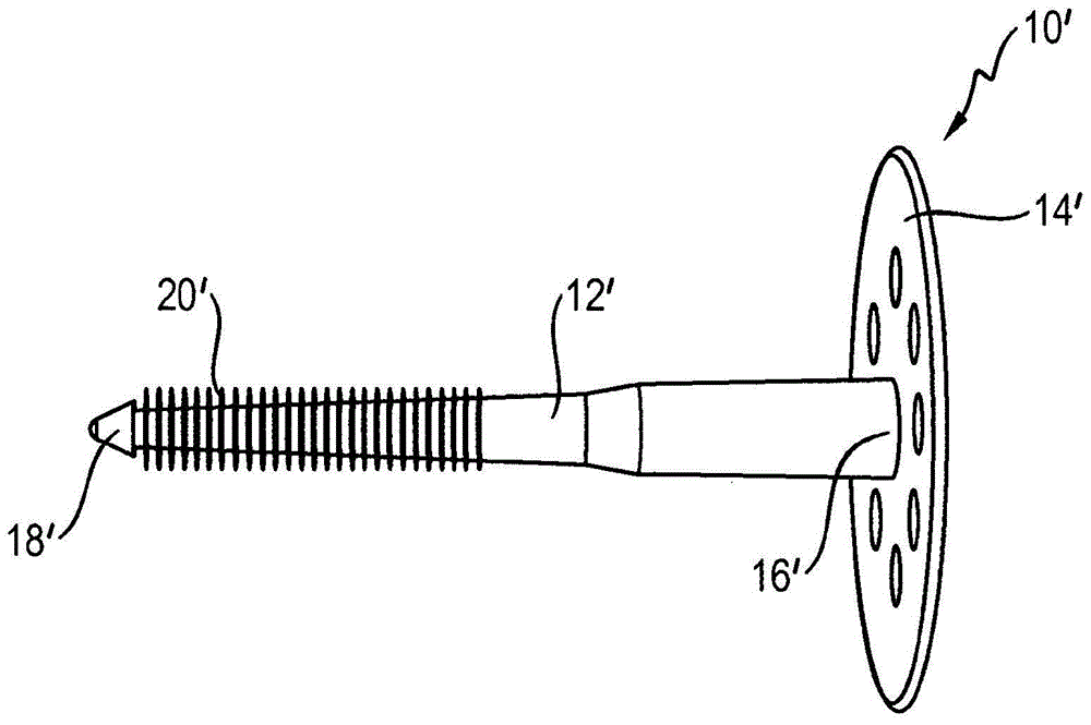
[0023] exist figure 1 A fastening element 10' for panels of insulating material according to the prior art is shown in Fig. 'superior. On the second end 18' of the rod body 12' opposite to the disc body 14', that is, on the tip of the rod body, a plurality of ribs 20' encircling in the circumferential direction are arranged.

[0024] The fastening element 10' is used for mounting insulation on walls or ceilings. To do this, the second end 18' of the rod 12' is pressed through the insulating material until the disc 14' lies flat on the surface of the insulating material. A second end 18' of the rod 12' protruding from the insulating material is pressed into an opening in the wall or ceiling. The diameter of this opening is smaller than the diameter of the shaft in the region of the rib 20'. The ribs 20' are deformed when the fastening element 10' is inserted into the opening, thus retaining the fastening element 10' frictionally in the opening.

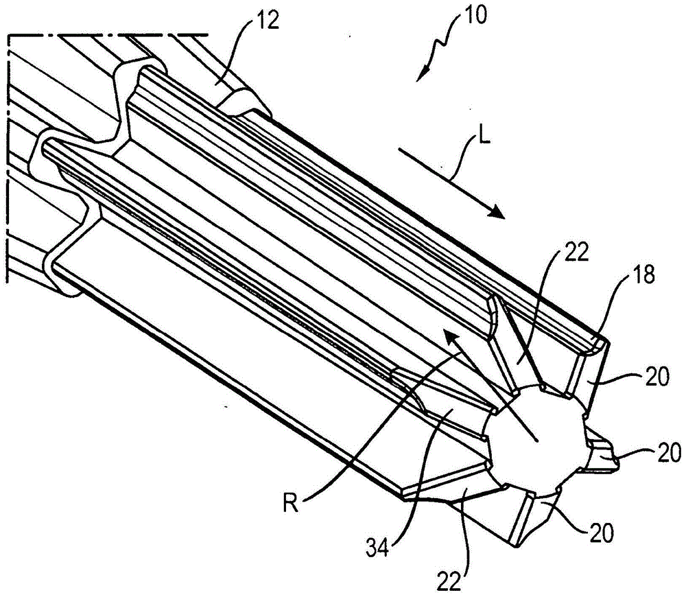
[0025] exist figure 2 A ...


PUM


Abstract

The invention relates to a securing element (10) for insulating materials, especially for insulating boards, comprising a shaft (12) and a plate provided on a first end of the shaft (12), radially protruding, longitudinally (L) extending ribs (20) being provided on the second end (18) of the shaft opposite the plate. The thickness of at least one rib (20) decreases at least in some sections in the radial direction (R) away from the shaft (12).

Description

technical field [0001] The invention relates to a fastening element for insulating material, in particular for panels of insulating material. Background technique [0002] For fastening insulating material, for example insulating material sheets, a fastening element is used which has an elongated shaft and a disk arranged at a first end. The rod is pressed through the insulation and fastened in the wall behind it, wherein the disk prevents the fastening element from being pushed completely through the insulation. In order to achieve a simple anchoring of the fastening element, radially protruding ribs extending in the longitudinal direction are provided on the second end of the rod body opposite the disk body. An opening for receiving the second end, ie the free end, of the rod is provided in the wall behind the insulating material. The diameter of this opening is slightly smaller than the diameter of the shaft in the region of the rib. When inserted into the opening, the...

Claims


Application Information

Patent Timeline
Patent Type & Authority Patents(China)
IPC IPC(8): F16B13/02E04B1/76F16B13/04F16B21/08
CPCF16B13/02E04B1/7633F16B13/045
Inventor T·蒋R·迈尔
Owner HILTI AG
Why Eureka
Try Eureka