


Quick Research
Generate reliable direction feasibility study reports for your R&D in just a few steps.

Technical Q&A
Discover and master advanced knowledge NOW. Basics, ideas, possibilities, all at once.

Find Solutions
As an expert in R&D theories, this can generate solutions to your technical problems instantly.

Evaluate Feasibility
Analyze your overall solution with one click, know your potential R&D risks in advance.

Monitor Landscape
Get weekly tech updates, stay abreast of the latest tech innovations and key insights.
Stop device of movable object
A stop device, mobile technology, applied to the legs of general furniture, furniture parts, household appliances, etc., can solve the problems of insufficient holding and small frictional resistance, and achieve the effect of sufficient holding force
- Summary
- Abstract
- Description
- Claims
- Application Information
AI Technical Summary
Problems solved by technology
Method used
Image

Examples
Embodiment Construction
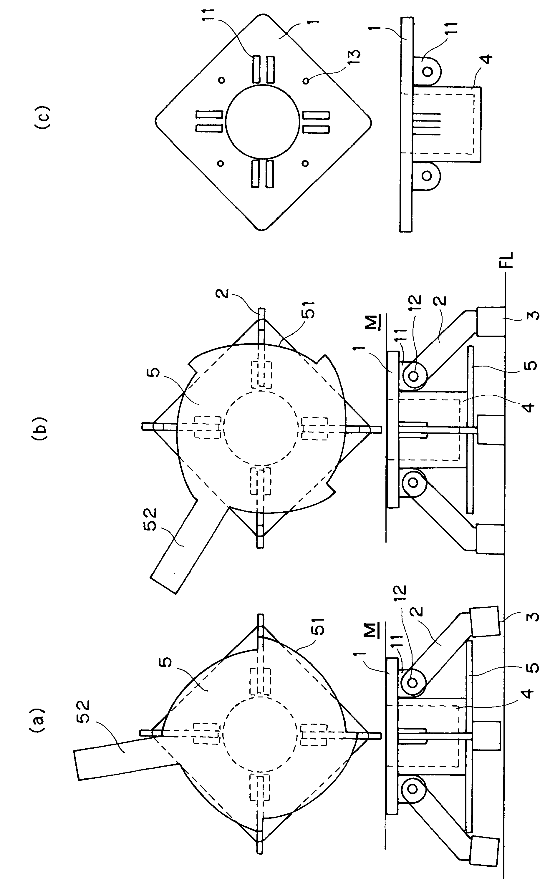
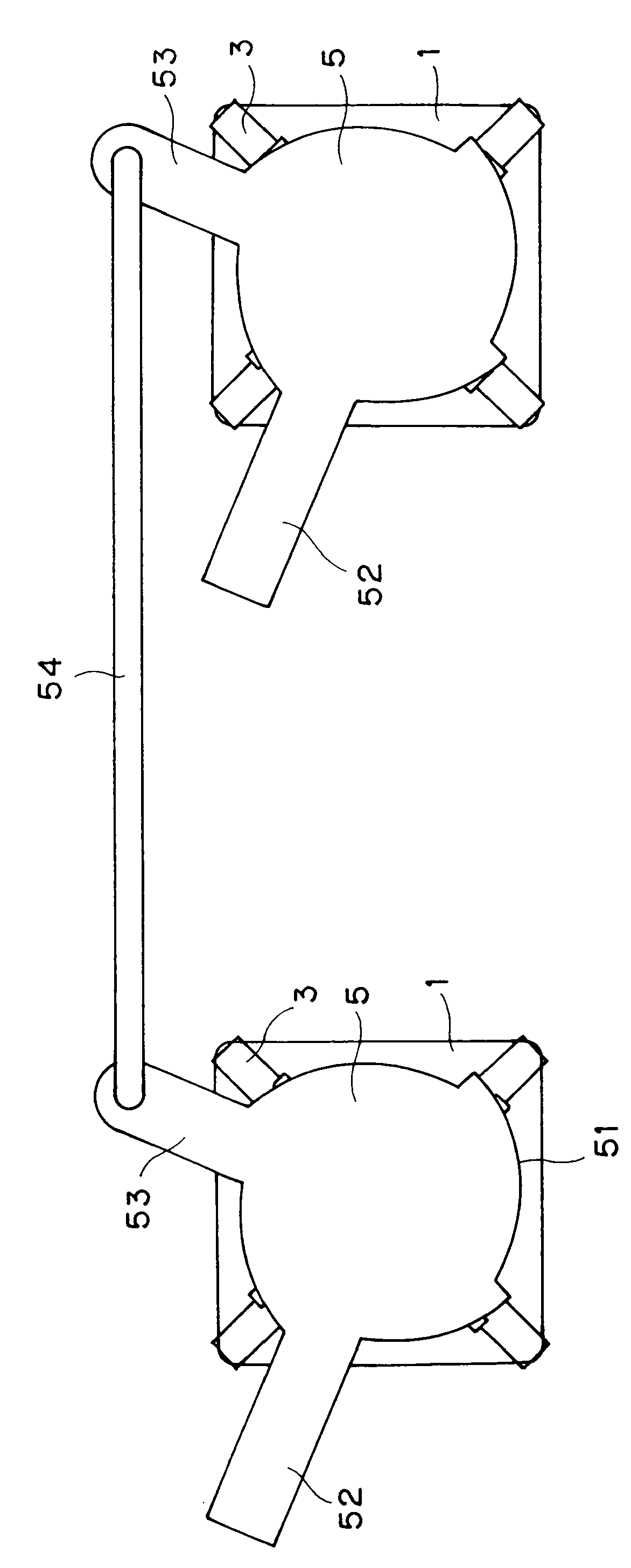
[0016] Next, embodiments of the stop device for a movable object according to the present invention will be described with reference to the drawings.
[0017] figure 1 An embodiment of the stopper for a movable object of the present invention is shown.
[0018] The stopping device of the mobile object is fixed on the main body 1 of the bottom surface of the mobile object M on which casters (not shown) are installed, and at least three or more are pivotally mounted at equal angular intervals through the lever piece 2 to swing freely. (In this embodiment, four examples have been shown, but as long as it is more than three, there is no limit to the number.) The grounding member 3 is used to support the rod piece 2 and lift the grounding member 3. The cam plate 5 is disposed on the main body 1 so as to be rotatable in a horizontal plane.
[0019] In this case, a support portion 11 for freely pivoting the lever piece 2 is protruded from the main body portion 1 , and the lever pie...
PUM
 Abstract
Description
Claims
Application Information
 - R&D Engineer
- R&D Manager
- IP Professional
- Industry Leading Data Capabilities
- Powerful AI technology
- Patent DNA Extraction
Browse by: Latest US Patents, China's latest patents, Technical Efficacy Thesaurus, Application Domain, Technology Topic, Popular Technical Reports.
© 2024 PatSnap. All rights reserved.Legal|Privacy policy|Modern Slavery Act Transparency Statement|Sitemap|About US| Contact US: help@patsnap.com