
Annular repeater system and network fault repairing method thereof

A repeater and ring technology, applied in the field of repeater networking, can solve problems such as unfavorable project maintenance, coverage paralysis, and inconvenient management, and achieve the effect of convenient query and management, convenient project maintenance, and convenient maintenance.

Active Publication Date: 2013-05-01
COMBA TELECOM SYST CHINA LTD
View PDF5 Cites 0 Cited by
  • Summary
  • Abstract
  • Description
  • Claims
  • Application Information

AI Technical Summary

Problems solved by technology

[0005]3. Daisy chain networking mode: it can make full use of optical fiber resources, and can share a near-end base station access control unit with multiple chains, and the equipment utilization rate is high. However, when there is a sudden failure or power failure at any level in the middle, all subsequent coverage will be paralyzed. Therefore, this networking method has poor stability and low intelligence.
[0006]4. Hybrid networking mode: it can adapt to a variety of different coverage area shapes, and the equipment utilization rate is high, but the network complexity will be increased due to this networking mode Large, resulting in inconvenient management, and at the same time, there is a problem of poor stability in the daisy chain structure
[0007] And in the Chinese patent "Repeater System and Data Interaction Method That Can Adaptively Adjust Networking Mode" with the published application number 200610036413.0, a The implementation of a ring network, as shown in Figure 5 , due to its imperfect monitoring system, when the network fails, the entire system will switch back and forth continuously, and it is easy to enter a state of endless loop, so the system stability is very poor
Since there is no fault reporting function in its monitoring system, the degree of intelligence is not high, which is not conducive to engineering maintenance

Method used


Image

  • Annular repeater system and network fault repairing method thereof
  • Annular repeater system and network fault repairing method thereof
  • Annular repeater system and network fault repairing method thereof

Examples


Embodiment 1

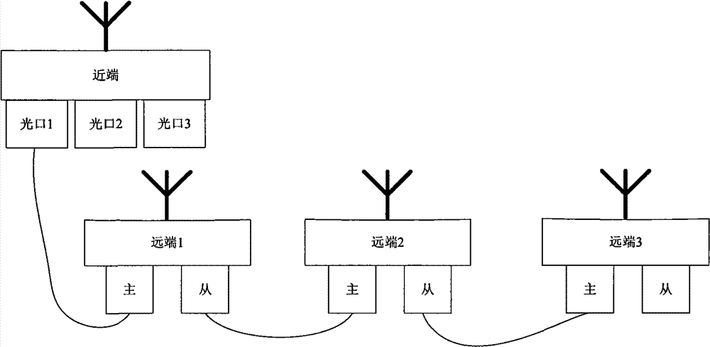
[0034] This embodiment proposes a ring repeater system, including a near-end base station access control unit and several remote radio frequency remote coverage units.

[0035] The near-end base station access control unit such as Figure 6 as shown, Figure 6 It is a schematic diagram of a near-end base station access control unit, including a coupling antenna, a radio frequency processing subsystem, an FPGA subsystem, a serial-to-parallel conversion 8B10B decoder, a power supply subsystem, a monitoring subsystem, a clock subsystem, and at least one pair of optical transceiver modules , wherein the at least one pair of optical transceiver modules includes a downlink forward end and an uplink reverse end. Wherein, the letter D is used to indicate the downlink forward end, and the letter U is used to indicate the uplink reverse end.

[0036] The remote radio remote coverage unit such as Figure 7 as shown, Figure 7 It is a schematic diagram of a remote radio remote coverag...

Embodiment 2

[0053] The invention also proposes a network fault recovery method based on the ring repeater system. In this embodiment, the ring repeater system applied to the network fault repair method is the same as the ring repeater system proposed in Embodiment 1.

[0054] The network fault repair method based on the ring repeater system specifically includes:

[0055] Step S1: Receive the reported status of the ring link, and select a network fault repair measure according to the location where the ring link is disconnected, if it is the uplink reverse end of the last remote radio remote coverage unit and the near-end base station access control unit If the link between them is disconnected, execute step S2; otherwise, if the link is disconnected at another position in the ring link, execute step S3. The failure of the entire ring link is divided according to the location where the communication link is disconnected, which can include two situations. One is the connection between the l...


PUM


Abstract

The invention provides an annular repeater system, wherein a near-end base station is connected into a control unit and is connected with far-end radio remote units of each level in the annular repeater system through optical fiber to form a closed annular link; in the annular repeater system, the optical fiber conveyed in the far-end radio remote covering unit is firstly connected with a light bypass unit, and then connected with the light bypass unit through a main optical interface; and the optical fiber coming out of the optical interface are respectively connected with the optical bypassunit and a next level far-end radio remote covering unit. The invention also provides a network fault repairing method of the annular repeater system. In the invention, the annular repeater system isestablished by an annular networking mode, thus realizing the report and auto-repairing of the operation condition of the annular link, being capable of realizing intelligentized management, and improving convenience content of the project maintenance and disaster resistance capability of the system.

Description

technical field [0001] The invention relates to repeater network technology, in particular to a ring repeater system and a method for repairing network faults of the ring repeater system. Background technique [0002] With the development of mobile communication, the site selection and installation of mobile communication base stations are becoming more and more difficult. In order to solve this problem, the repeater system is often used in the network to reduce the cost of base station construction and optimize network coverage. However, the current repeater system generally adopts one-to-one single-point connection, or one-to-many star topology, or a bus topology similar to daisy chain, or a mixture of daisy chain and star topology. The four networking modes of the structure. Specific as Figure 1 to Figure 4 as shown, figure 1 For one-to-one network mode, figure 2 It is a star network, image 3 For daisy chain networking, Figure 4 It is a hybrid networking mode. ...

Claims


Application Information

Patent Timeline
Patent Type & Authority Patents(China)
IPC IPC(8): H04B7/14H04B10/2575H04L12/24H04B10/03
Inventor 欧阳珍学陈尧左延麟
Owner COMBA TELECOM SYST CHINA LTD
Learn More