
Device for displacing oil underground, preventing reflow and automatically relieving pressure

An automatic drainage and oil displacement technology, which is applied to wellbore/well valve devices, wellbore/well components, earthwork drilling and production, etc., can solve the problems of increasing economic investment in operation procedures, and achieve simple structure, long service life, The effect of saving workover cost

Inactive Publication Date: 2010-07-07
XI'AN PETROLEUM UNIVERSITY +1
View PDF6 Cites 2 Cited by
  • Summary
  • Abstract
  • Description
  • Claims
  • Application Information

AI Technical Summary

Problems solved by technology

At present, for oil wells with too low formation energy, a one-way valve is generally installed on the surface pipeline near the wellhead to prevent the pipeline fluid from backflowing into the oil well after shutdown, and a one-way valve is installed on the upper end of the driving equipment to prevent pipeline fluid from Backfilling of the oil well prevents the motor from reversing due to the backflow of the fluid. At the same time, it is equipped with a drainer for pressure relief. This requires that the drainer has a high airtightness during normal production, and the oil pipe must be pulled out after the pressure is relieved. Updating the downhole oil drainer increases redundant operating procedures and unnecessary economic investment,

Method used


Image

  • Device for displacing oil underground, preventing reflow and automatically relieving pressure
  • Device for displacing oil underground, preventing reflow and automatically relieving pressure

Examples


Embodiment Construction

[0010] In order to further disclose the technical solutions of the present invention, the following will be described in detail through examples in conjunction with the accompanying drawings:

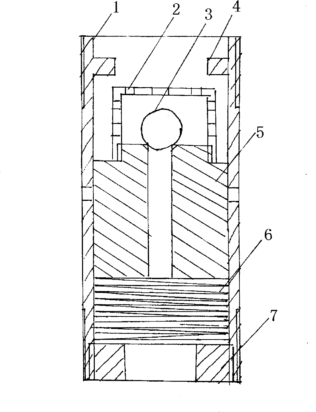
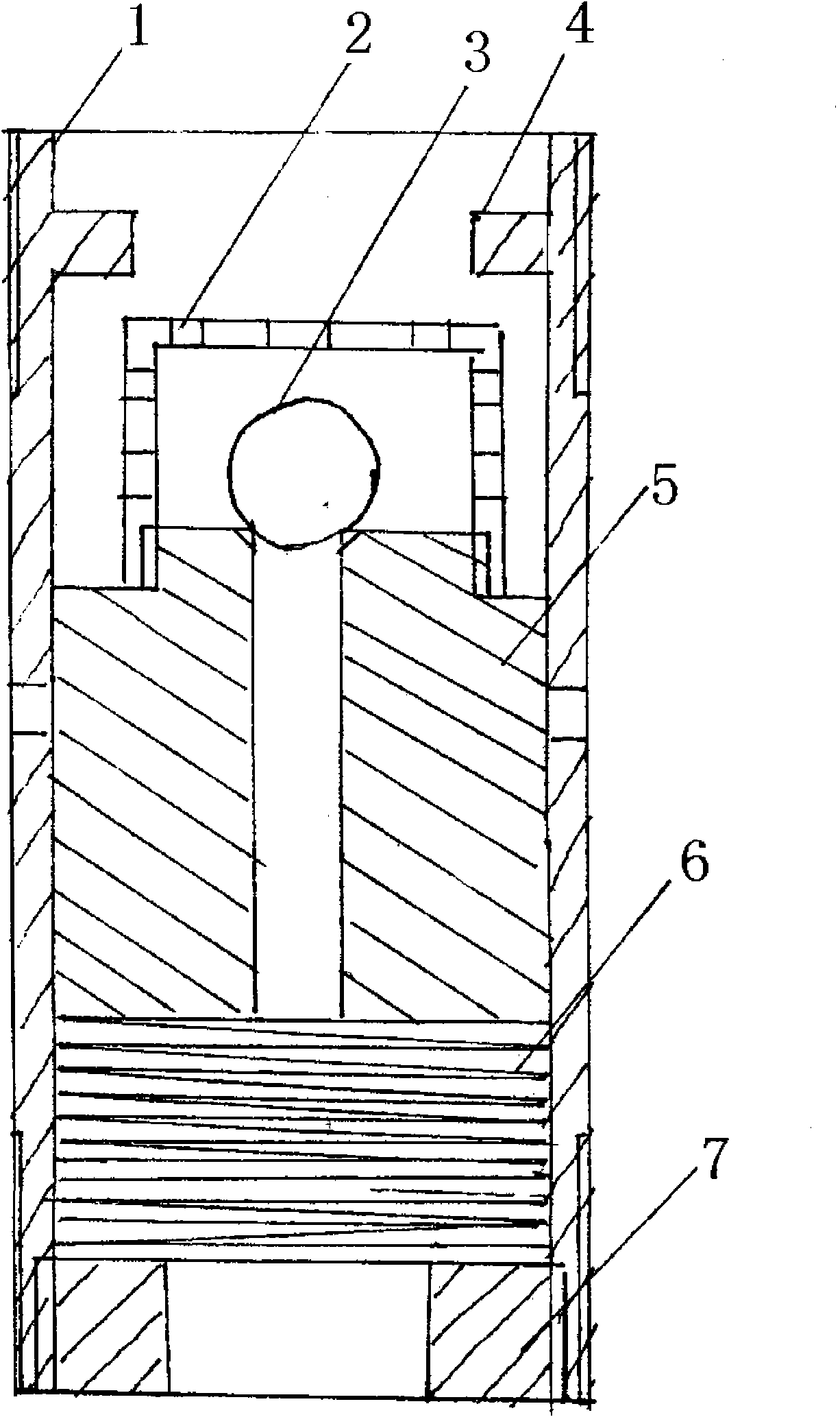
[0011] The present invention is mainly composed of a body 1, a sealing ball cover 2, a sealing ball 3, a slider 5, a spring 6, a limit block 4 and a spring seat 7. Thread, the inner circumference of the upper part is provided with a number of limit blocks 4, the inner circumference of the lower part is provided with female threads, and the center of the upper end with a sealing ball cover 2 is provided with a core hole and the upper part of the center hole is provided with a sealing ball 3 in the middle of the body. The cylindrical slider 5 has a coil spring 6 at the middle and lower part, and a spring seat 7 threadedly connected with the body at the lower part, and several oil drain holes are arranged at the middle part of the body; the dynamic sealing fit between the slider and the bod...


PUM


Abstract

The invention discloses a device for displacing oil underground, preventing reflow and automatically relieving pressure, which mainly comprises a body, a sealing ball cover, a sealing ball, a sliding block, a spring, limiting blocks and a spring seat, wherein the body is set into a cylinder shape; the circumferences of the upper part and the lower part of the body are provided with male threads; the inner circumference of the upper part is provided with a plurality of limiting blocks; the inner circumference of the lower part is provided with female threads; the center the upper end part of which is provided with the sealing ball cover is provided with a center hole in the middle of the body; the cylindrical sliding blocks of the sealing ball is arranged at the upper part of the center hole; a spiral spring is arranged at the middle lower part of the center hole; the spring seat which is in threaded connection with the body is arranged at the lower part of the center hole; the middle of the body is provided with a plurality of oil draining holes; the sliding blocks and the body are in movable sealing fit; male threads at the lower end of the body are connected with threads of an outlet pipe of an underground lifting pump; and male threads at the upper end of the body are connected with an oil pipe column. The invention has the advantages of simple structure, reliable sealing, no soft sealing member, long service life, no need of replacement, reduction of times for pulling the oil pipe and well repairing cost economization.

Description

1. Technical field [0001] The invention relates to a downhole oil displacement preventing backflow and automatic pressure relief device which can timely release excess energy accumulated in the well after downhole oil displacement lifting equipment stops working, prevent backflow, prevent motor reversal and release the pressure of the tubing string in time. 2. Background technology [0002] In the downhole driving and lifting crude oil process production, when the shutdown is shut down, the energy accumulated in the production process will be released, and the fluid stored in the tubing will generate elastic energy, and the output fluid in the tubing and the output pipeline will form with the fluid in the casing. Pressure difference, etc. cause the drive pump to become a hydraulic motor, which not only damages the components of the drive device but also endangers the safety of the equipment. At present, for oil wells with too low formation energy, a one-way valve is generall...

Claims


Application Information

Patent Timeline
Patent Type & Authority Applications(China)
IPC IPC(8): E21B34/08
Inventor 曲占庆蒋海岩田相雷袁世宝齐宁蔡文斌刘小波杨海滨樊波梁涛翟恒立卢辉吴婷
Owner XI'AN PETROLEUM UNIVERSITY
Learn More