
Method and tool for decementing light machine assembly parts

A technology for dismantling tools and assembling parts, applied in manufacturing tools, hand-held tools, etc., can solve the problems of dimensional deformation, low shear strength, structural damage, etc., and achieve the effect of reducing the risk of adhesive glue and simple and convenient operation.

Inactive Publication Date: 2010-07-07
XIAN MICROMACH TECH CO LTD
View PDF0 Cites 7 Cited by
  • Summary
  • Abstract
  • Description
  • Claims
  • Application Information

AI Technical Summary

Problems solved by technology

[0004] The invention proposes a deglue method and tool after high-strength glue bonding light machine parts. The characteristics of strength, combined with the application of shear force by the labor-saving mechanism, solves the technical problems such as pollution of the mirror film layer, dimensional deformation, and structural damage in the existing optical-mechanical assembly disassembly technology.

Method used


Image

  • Method and tool for decementing light machine assembly parts
  • Method and tool for decementing light machine assembly parts
  • Method and tool for decementing light machine assembly parts

Examples


Embodiment Construction

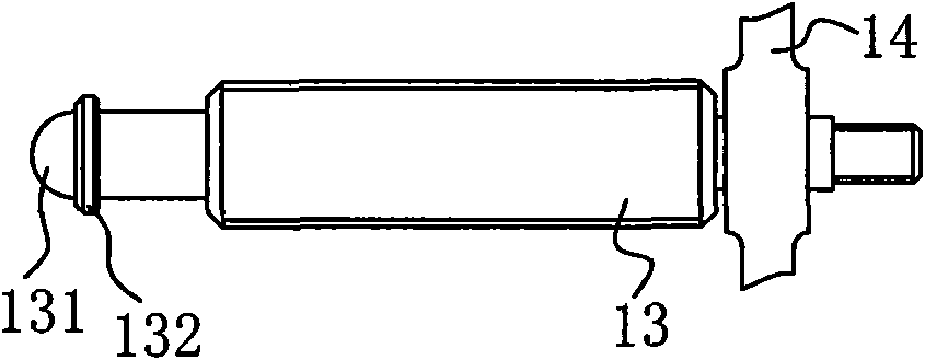
[0031] see figure 1 and figure 2 , the deglue tool of the present invention includes a base plate 3, a fixed assembly and a thrust assembly; the fixed assembly includes a baffle plate 4 fixed on the left side of the base plate 3, and two limit seats 9 arranged on the right side of the base plate 3; the base plate 3 is provided with multiple A row of screw holes, the baffle plate 4 is fixed in the screw holes at different positions to adapt to different sizes of the gluing machine assembly 1 to be dismantled, and the limit seat 9 is provided with a device that can press the gluing machine assembly 1 to be disassembled to the baffle plate 4 adjusting screw 91; the thrust assembly includes a guide frame 11, a bracket 12, a push rod 13, a push rod pressing plate 10, a push claw 8, two push blocks 6, and a wrench 14; a threaded hole 121 is provided in the bracket 12; see Figure 3 to Figure 6 , the circumferential side of the push rod 13 is provided with a screw thread matched wi...


PUM


Abstract

The invention relates to a method and a tool for decementing light machine assembly parts, comprising the following steps: 1) fixing a light machine assembly part 1 to be decemented on a decementing tool; 2) placing the light machine assembly part 1 to be decemented and the decementing tool into a high and low temperature chamber and raising temperature to 60 DEG C to 80 DEG C at constant speed in 30min then keeping the temperature for 30min; 3) opening the door of the high and low temperature chamber, slowly rotating a wrench in the high and low temperature chamber to enable a bucking bar to move leftwards until optical glass breaks away from a framing member; 4) cooling the high and low temperature chamber to room temperature and then taking out optical glass, the framing member and the decementing tool. With the method and tool of the invention, pollution of mirror surface film layer, size distortion and structural damage in the existing technology for decementing the light machine assembly parts are solved. In addition, the method and tool of the invention have the advantages of simple and convenient operation and no influence on physical property of optical elements.

Description

technical field [0001] The invention relates to a glue-removing method and a special tool for an assembly of optical glass and mechanical parts bonded by high-strength structural glue. Background technique [0002] The use of bonding technology in optical instruments has received widespread attention and application at home and abroad. The parts in the optomechanical assembly are bonded by high-strength structural adhesive, which can withstand shock and vibration, has the characteristics of high bonding strength, stability and reliability, and has certain flexibility, so it has been widely used. However, due to its high bonding strength, if rework is required during the assembly and adjustment process, the force required to remove the glue is also quite large. Through the test of an epoxy resin structural adhesive, its tensile strength is about 29MPa, and its shear strength is about 20.5MPa. Using the characteristic that its shear strength is lower than the tensile strength...

Claims


Application Information

Patent Timeline
Patent Type & Authority Applications(China)
IPC IPC(8): B25B27/00
Inventor 李燕胡永明李英才许嘉源吴萌源
Owner XIAN MICROMACH TECH CO LTD
Learn More