
Device and method for internal pressure forming of reducer pipes

A technology of variable diameter pipe and internal pressure, which is applied in the field of processing and forming devices for variable diameter pipe fittings, can solve the problems of difficulty in guaranteeing forming accuracy, high processing cost, and numerous working units, and achieve forming accuracy assurance, fewer control components, and simple structure Effect

Inactive Publication Date: 2010-07-07
HARBIN UNIV OF SCI & TECH
View PDF0 Cites 20 Cited by
  • Summary
  • Abstract
  • Description
  • Claims
  • Application Information

AI Technical Summary

Problems solved by technology

[0003] The purpose of the present invention is to solve the problem that the realization of the high pressure forming in the existing variable diameter tube requires precise control of the matching between the mold clamping and the loading on both sides, there are many working units, the forming accuracy is difficult to guarantee, and the processing cost is high. A device and method for internal pressure forming of variable diameter pipe fittings

Method used


Image

  • Device and method for internal pressure forming of reducer pipes
  • Device and method for internal pressure forming of reducer pipes
  • Device and method for internal pressure forming of reducer pipes

Examples


specific Embodiment approach 1

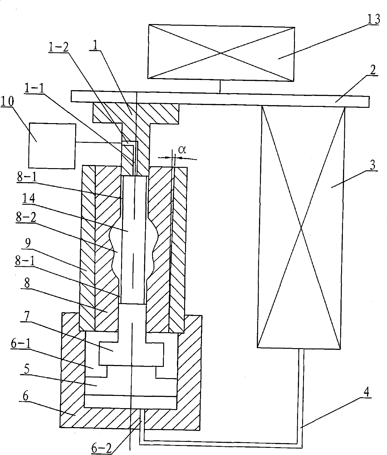
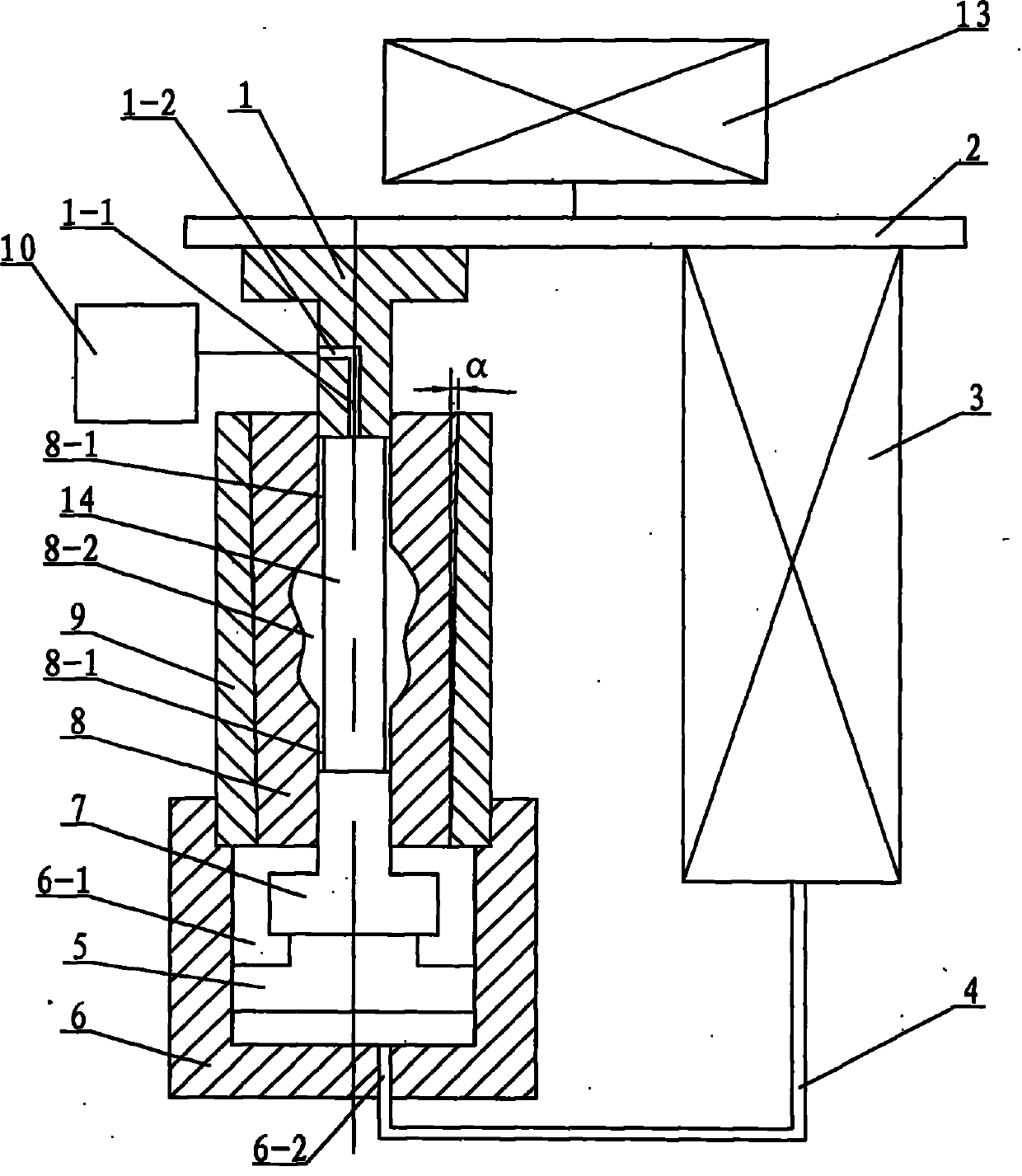
[0008] Specific implementation mode one: combine figure 1 Describe this embodiment, this embodiment includes upper punch 1, workbench 2, plunger cylinder 3, high-pressure oil pipe 4, base 5, mold base 6, lower punch 7, die 8, die sleeve 9 and hydraulic booster Device 10, the die 8 is composed of two semi-conical frustums arranged symmetrically, the central axis of the die 8 is provided with a die cavity 8-1, the die 8 is installed in the die sleeve 9, and the upper end surface of the die frame 6 There is a mold cavity 6-1, and the middle section of the die cavity 8-1 is provided with a variable-diameter cavity 8-2, and the base 5, the lower punch 7 and the mold sleeve 9 are installed on the mold base 6 sequentially from bottom to top. 6-1, and the upper end of the lower punch 7 is located in the corresponding die cavity 8-1, the upper punch 1 is set above the die 8, and the lower end of the upper punch 1 is located in the corresponding die cavity In 8-1, an oil hole 1-1 is pr...

specific Embodiment approach 2

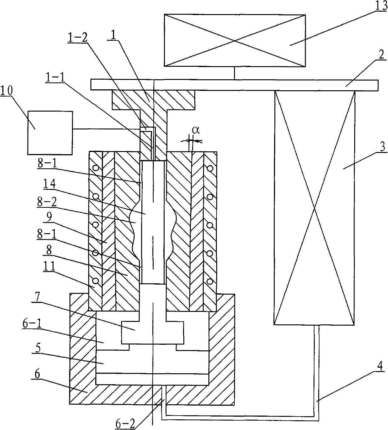
[0009] Specific implementation mode two: combination figure 2 This embodiment is described. The difference between this embodiment and the first embodiment is that: the device is further provided with a heating device 11 , and the heating device 11 is set on the outer surface of the mold case 9 . Such a design enables the reduced-diameter pipe fittings made of materials such as magnesium alloys and superhard aluminum alloys with poor room temperature plasticity to be realized by the device of the present invention. Other components and connections are the same as those in the first embodiment.

specific Embodiment approach 3

[0010] Specific implementation mode three: combination figure 2 Describe this embodiment, this embodiment is realized through the following steps: Step 1: First, install the base 5, the lower punch 7 and the die sleeve 9 equipped with the die 8 from bottom to top in the cavity 6 on the mold frame 6- 1, and place the upper end of the lower punch 7 in the corresponding die cavity 8-1; Step 2: load the tube blank 14 from the upper end of the die 8 into the die cavity 8-1; place the upper punch The lower end of the head 1 is placed in the corresponding die cavity 8-1, and the lower end surface of the upper punch 1 closes the upper end surface of the tube blank 14; Step 3: Put the components completed in Step 1 and Step 2 under normal pressure On the working table on the machine, the upper end surface of the working table 2 is connected with the hydraulic cylinder 13 on the ordinary press; Step 4: Drive the working table 2 downward through the hydraulic cylinder 13 to apply force ...


PUM


Abstract

The invention relates to a device and method for internal pressure forming of reducer pipes. The invention aims to solve the following problems: matching among die assembly, loading at both sides and the like needs to be controlled for realizing internal high pressure forming of the existing reducer pipes; the working units are various; the forming precision is difficult to ensure; and the processing cost is higher. The device is assembled by an upper punch, a workbench, a plunger type cylinder, a high-pressure oil pipe, a base, a die set, a lower punch, female dies, die sleeves and a hydraulic supercharger and has reducer die cavities. The method comprises the following steps: assembling the base, the die set, the lower punch and the die sleeves mounted with the female dies; placing a pipe blank into a female die cavity; placing the upper punch into the pipe blank; extruding the pipe blank by an ordinary press; pushing the base and the lower punch to ascend by hydraulic oil; and continuously supercharging the liquid in the cavity of the pipe blank under forming by the hydraulic supercharger until the outer wall of the pipe blank is fit with the inner walls of the female die cavity and the reducer die cavities, thus completing internal pressure forming of the reducer pipes. The invention is used for processing and forming the reducer pipes.

Description

technical field [0001] The invention relates to a processing and forming device and method for variable-diameter pipe fittings. Background technique [0002] One of the main ways to reduce the weight of the structure is to adopt the lightweight structure of "substituting empty space for solid", which can not only achieve the purpose of reducing weight and saving materials, but also make full use of the strength and stiffness of materials. Internal high pressure forming is an advanced manufacturing process for hollow variable cross-section lightweight components developed in response to this demand, which can integrally form hollow components with varying cross-sections along the axis at one time. Compared with the stamping welding process, the internal high pressure forming has the following main advantages: improve the integrity of components, reduce the number of parts and molds, reduce mold costs, reduce the amount of subsequent machining and assembly welding, and improve...

Claims


Application Information

Patent Timeline
IPC IPC(8): B21D26/02B21D37/16
Inventor 李峰初冠南卢为刘晓晶李超
Owner HARBIN UNIV OF SCI & TECH
Learn More