
Forming method of bending wave steel webs and special module

A technology of corrugated steel webs and forming methods, which is applied in the direction of forming tools, manufacturing tools, metal processing equipment, etc., can solve the problems of poor quality of finished products, low production efficiency of corrugated steel webs, small power configuration of presses, etc., and achieve saving Energy, production accuracy, easy control, and small power configuration

Active Publication Date: 2010-07-07
ZHEJIANG CTB WAVEFORM STEEL WEB
View PDF1 Cites 16 Cited by
  • Summary
  • Abstract
  • Description
  • Claims
  • Application Information

AI Technical Summary

Problems solved by technology

[0004] The present invention aims at the disadvantages of low production efficiency and poor quality of finished products in the prior art of corrugated steel webs, and provides an easy-to-control production precision, which uses three indenters to press successively, so that the power configuration of the press is relatively small Bending corrugated steel web forming method and special mold

Method used


Image

  • Forming method of bending wave steel webs and special module
  • Forming method of bending wave steel webs and special module
  • Forming method of bending wave steel webs and special module

Examples


Embodiment 1

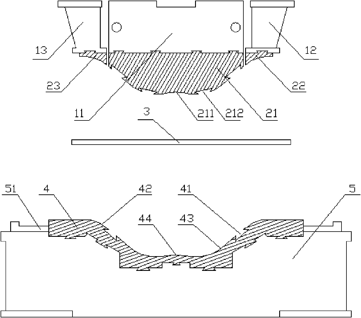
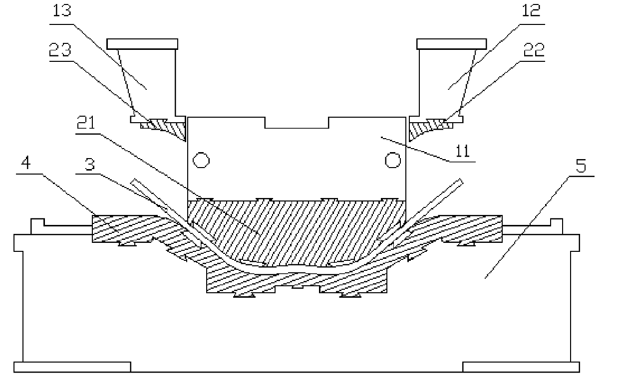
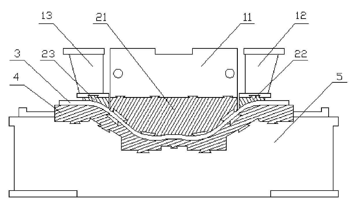
[0031] Bending corrugated steel web forming method and special mold, such as Figure 1 to Figure 3 As shown, the bending type corrugated steel web forming method comprises the following steps:

[0032] a. Put the steel plate 3 that has been cut after turning over the sample into the mold according to the inflection point of the corner;

[0033] b. The middle press 11 is loaded, and the middle press 11 pushes the middle pressure head 21 to bend the steel plate 3 for the first time;

[0034] c. At the same time, the piezoresistor on the middle pressure head 21 and the lower mold 4 monitors the stress on the steel plate 3. When the force on the steel plate 3 is within the set range, that is, when the steel plate 3 is formed into a specified shape, the pressure The sensitive resistor transmits the data to the control center, and the control center controls the stopping of the loading of the press 11 and starts holding the pressure;

[0035] d. The control center controls the pre...

Embodiment 2

[0047] Bending corrugated steel web forming method and special mold, such as Figure 1 to Figure 3 As shown, the bending type corrugated steel web forming method comprises the following steps:

[0048] a. Put the steel plate 3 that has been cut after turning over the sample into the mold according to the inflection point of the corner;

[0049] b. The middle press 11 is loaded, and the middle press 11 pushes the middle pressure head 21 to bend the steel plate 3 for the first time;

[0050] c. At the same time, the piezoresistor on the middle pressure head 21 and the lower mold 4 monitors the stress on the steel plate 3. When the force on the steel plate 3 is within the set range, that is, when the steel plate 3 is formed into a specified shape, the pressure The sensitive resistor transmits the data to the control center, and the control center controls the stopping of the loading of the press 11 and starts holding the pressure;

[0051] d. The control center controls the pre...


PUM


Abstract

The present invention relates to a forming making method of shear walls applied to roadway bridges, railway bridges and reinforced concrete construction and various wave steel webs of channel reinforced concrete supporting engineering, and a special module. The present invention discloses a forming method of bending wave steel webs, and a special module. When wave steel webs are formed, a section pressing method that time is order, and space is divided. The special module of bending wave steel web forming comprises a press machine, a punch head arranged on the press machine, a base and a lower module arranged on the base, wherein a location block of the lower module is also arranged on the base; the press machine comprises a middle press machine, a right press machine and a left press machine; a middle press head is arranged on the middle press machine; a right press head is arranged the right press head; and a left press head is arranged on the left press machine. The making precision of wave steel webs is easy to control, and three press heads are used to press in succession to enable the power of the press machine small.

Description

[0001] Bending corrugated steel web forming method and special mold technical field [0002] The invention relates to a forming manufacturing method and a special mold for various corrugated steel webs applied to highway bridges, railway bridges, shear walls of reinforced concrete buildings and reinforced concrete support projects of tunnels, and in particular to forming of bent corrugated steel webs Method and special mold. Background technique [0003] The key parts of the traditional corrugated steel web bending forming technology: the inner mold and the outer mold only use a mold with a certain radius, so that the forming power of the corrugated steel web is required to be large, and the rebound difference is large. For example, the patent number applied by Zhuang Tiancai is 200820041263.7 The utility model patent, the application date is August 11, 2008, the announcement date is August 19, 2009, the announcement number is CN201291256, and the name is special-shaped plat...

Claims


Application Information

Patent Timeline
Patent Type & Authority Applications(China)
IPC IPC(8): B21D5/06B21D37/10B21D37/12B21D37/14B21D37/04
Inventor 孙天明陈惠国
Owner ZHEJIANG CTB WAVEFORM STEEL WEB
Learn More