
Method for coordinating interferences among HSUPA substricts in TD - SCDMA system

A TD-SCDMA, inter-cell interference technology, applied in transmission systems, wireless communications, electrical components, etc., can solve the problems of increasing mutual interference, unable to reduce transmission power, and difficult to control the level of interference in adjacent cells The effect of throughput

Inactive Publication Date: 2010-06-30
ZTE CORP
View PDF0 Cites 11 Cited by
  • Summary
  • Abstract
  • Description
  • Claims
  • Application Information

AI Technical Summary

Problems solved by technology

With the gradual expansion of the commercial scale of HSUPA, since the TD-SCDMA system adopts the same-frequency networking method, this power authorization method in HSUPA technology is likely to cause increased mutual interference in the uplink direction between adjacent cells, resulting in continuous interference in the entire network. Raise, which in turn will seriously affect the uplink throughput of the entire network
Although the base station (Node B) tries to control the interference level of the cell within the threshold range of the ROT by reducing the transmit power of the users in the cell, in fact, because the TD-SCDMA system adopts the joint detection technology in the uplink direction, Most of the interference between users in the cell can be eliminated by joint detection technology. The total interference in the cell mainly comes from the same-channel interference of adjacent cells. Because the architecture of the 3G system determines that the base station (Node B) cannot know whether it is Which adjacent cells cause strong interference to the current cell, so the base station (Node B) cannot affect the interference source of the adjacent cell to effectively control, the base station (Node B) can only reduce the transmission power of the user in the cell but cannot reduce the interference of the adjacent cell This adjustment method is actually very difficult to effectively control the interference level within the ROT threshold range

Method used


Image

  • Method for coordinating interferences among HSUPA substricts in TD - SCDMA system
  • Method for coordinating interferences among HSUPA substricts in TD - SCDMA system
  • Method for coordinating interferences among HSUPA substricts in TD - SCDMA system

Examples


Embodiment Construction

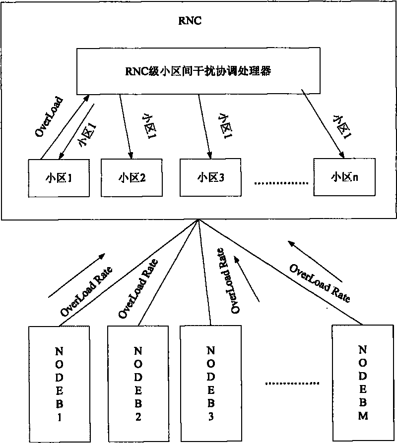
[0032] This technical solution introduces a new public measurement E-PUCH overload rate, which is defined as follows:

[0033] E-PUCH Overload Ratio (E-PUCH OverLoad Ratio): base station (Node B) within a specified period counts the ratio of the average interference of time slots carrying E-PUCH resources in each 5ms TTI exceeding the ROT threshold to the total number of TTIs within a specified period ratio. The measurement can support periodic reporting.

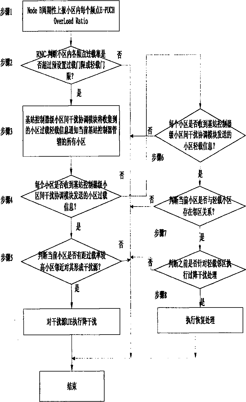
[0034] If the overload rate reported by the base station (Node B) is at a high level for a sustained period of time, it is considered that the base station (Node B) has been unable to control the interference level of this frequency point within a reasonable range through the power authorization method in the cell Inside. Inter-cell interference coordination strategies at the base station controller (RNC) level need to be activated

[0035] Step 101: The base station (Node B) periodically reports the E-PUCH OverLoad Rati...


PUM


Abstract

The present invention provides new public measurement of E-PUCH Overload Ratio, which is defined as the following: the E-PUCH Overload Ratio: the ratio of times that the average interference of time gaps for loading E-PUCH source in every 5ms TTI is above ROT threshold to the total number of TTI in an appointed period is counted in a base station (Node B) in an appointed period. The new public measurement can support period reporting. By the present invention, interference sources in nearby regions which bring the overload ratio of some subdistrict to high can be detected by the tactic of grades of a base station controller (RNC), and the effect of the interference sources is reduced by reasonable measures. Disadvantages that the base station (Node B) can not know the information of the nearby regions, and a high overload ratio condition of the subdistrict can not be solved by controlling the interference of the nearby regions are solved well, and the HSUPA throughput ratio of a whole net can be effectively improved.

Description

Technical field: [0001] The present invention relates to a Time Division-Synchronous Code Division Multiple Access-TD-SCDMA system, in particular to a kind of inter-cell interference in the High Speed ​​Uplink Packet Access (HSUPA-High Speed ​​Uplink Packet Access) technology Coordinate technology. Background technique: [0002] The third-generation mobile communication system introduces the high-speed uplink packet access feature. In the HSUPA feature, a higher rate is provided by introducing adaptive coding and modulation (AMC: Adaptive Modulation and Coding), hybrid automatic repeat request (HARQ: Hybrid Automatic RetransmissionReq user) technology and related technologies for reducing network processing delay Uplink packet service rate, improve spectrum utilization efficiency. [0003] In HSUPA technology, in order to enable users to obtain maximum throughput in the uplink direction, the base station (Node B) always tries to grant as many power resources as possible fo...

Claims


Application Information

Patent Timeline
IPC IPC(8): H04W24/10H04W72/02H04B1/707
Inventor 周捷
Owner ZTE CORP
Learn More