
Rapid low-cost water level lowering well sealing device and construction method thereof

A dewatering well, low-cost technology, applied in infrastructure engineering, construction, etc., can solve the problems of poor sealing effect and long sealing construction period of dewatering wells, achieving good sealing effect, reducing construction costs, and saving costs.

Inactive Publication Date: 2010-06-30
CHINA CONSTR SECOND ENG BUREAU LTD +1
View PDF0 Cites 26 Cited by
  • Summary
  • Abstract
  • Description
  • Claims
  • Application Information

AI Technical Summary

Problems solved by technology

[0008] The purpose of the present invention is to provide a fast and low-cost closed dewatering well device and its construction method, to solve the technical problems of the existing dewatering well closed construction period is long and the sealing effect is not good

Method used


Image

  • Rapid low-cost water level lowering well sealing device and construction method thereof
  • Rapid low-cost water level lowering well sealing device and construction method thereof
  • Rapid low-cost water level lowering well sealing device and construction method thereof

Examples


Embodiment 1

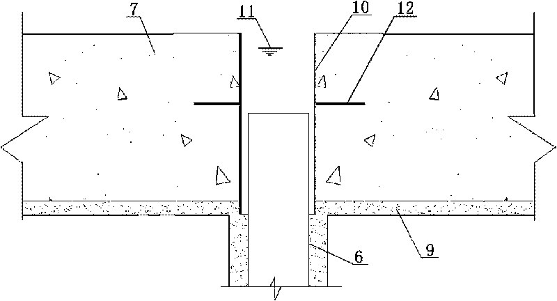
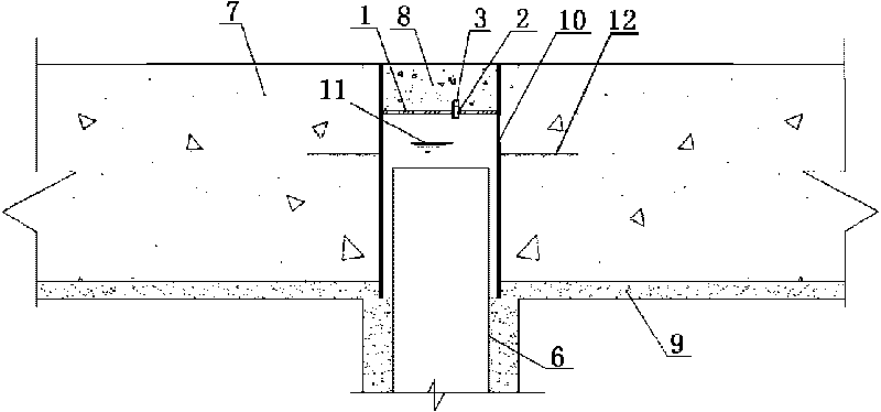
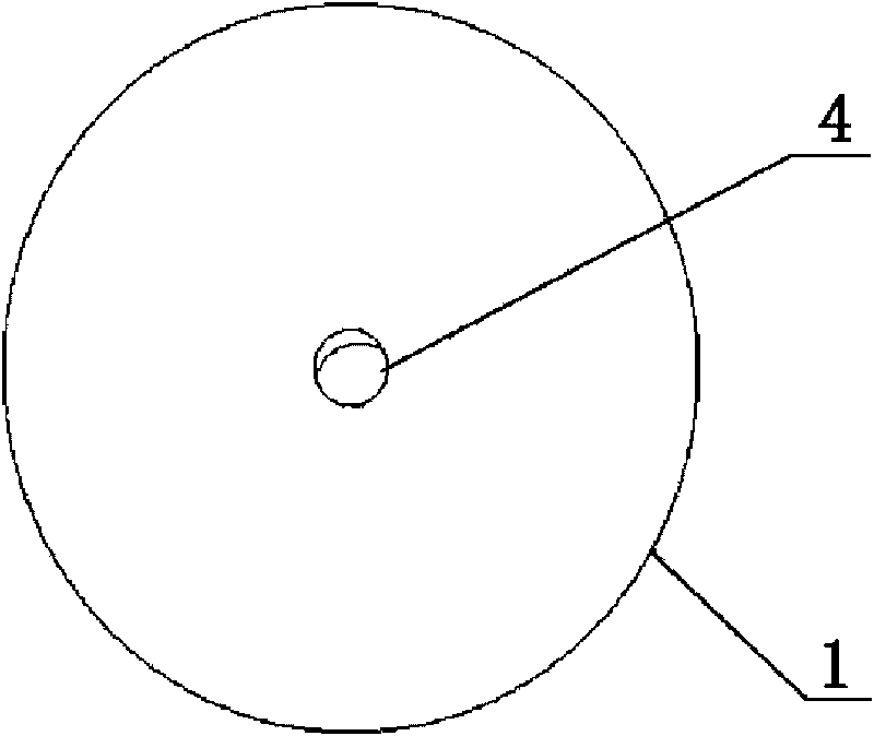
[0035] Embodiment one, see figure 1 , figure 2 As shown, this fast and low-cost closed dewatering well device is located in the upper mouth of the dewatering well 6, and a wellhead pipe 10 is fixed on the upper mouth of the dewatering well 6, and the periphery of the wellhead pipe is welded with a pre-embedded plate 12, and the pre-embedded plate 12 It is an annular plate or a finned plate. The pre-embedded plate is pre-embedded in the floor concrete 7, the wellhead pipe 10 is welded with a head steel plate 1, and there is at least one water gushing hole 4 on the head steel plate, and a sleeve 2 is welded on the water gushing hole, and the sleeve 2 and the plug 3 are threaded connect.

[0036] see Figure 3-Figure 5 As shown, the sleeve 2 has an internal thread, the plug 3 has an external thread, and the top of the plug is connected with a tightening nut 5 . Have a gushing hole 4 on the head steel plate.

Embodiment 2

[0037] Embodiment two, see Figure 6-Figure 8 As shown, the difference from the first embodiment is that the sleeve 2 has external threads, the plug 3 is in the shape of a screw cap with internal threads, and the top of the plug is connected with a tightening nut 5 . Have three gushing holes 4 on the head steel plate.

[0038] Construction method of the present invention sees figure 1 , figure 2 Shown:

[0039] Step 1, a wellhead pipe is fixed on the upper mouth of the dewatering well, and the periphery of the wellhead pipe is welded with a pre-embedded plate 12, and the pre-embedded plate is pre-embedded in the floor concrete 7, and the upper mouth of the wellhead pipe is flush with the floor concrete 7;

[0040] Step 2, weld the head steel plate 1 in the wellhead pipe, weld the periphery of the head steel plate to the inner wall of the wellhead pipe, the distance between the head steel plate and the upper opening of the wellhead pipe is greater than 100mm, and at least o...


PUM


Abstract

The invention relates to a rapid low-cost water level lowering well sealing device and construction method thereof. The device is arranged in the upper mouth of the water level lowering well, the upper mouth of the water level lowering well is fixed with a well mouth pipe, the periphery of the well mouth pipe is welded with embedded plates, the embedded plates are embedded in concrete of base plate, the well mouth pipe is internally welded with an end enclosed steel plate, the end enclosed steel plate is provided with at least one water bursting hole, the water bursting hole is welded with a sleeve, and the sleeve is connected with a core plug by screw thread. The invention realizes sealing of water level lowering well by welding of parts and threaded connection, osmosis path of underground water is completely blocked, and no broken stone or concrete is required to be refilled in the well. Sealing effect is good, the aim of being watertight can be realized; construction is convenient, construction speed is rapid, well sealing operation can be completed in 20 minutes generally; construction cost can be reduced, and by adopting the method, over 50% of cost per well can be saved compared with a common method. The invention is applicable to water draining construction of foundation, can be adopted when sealing water level lowering well of foundation pit and also can be used in other fields.

Description

technical field [0001] The invention relates to a foundation drainage device and a construction method thereof. Background technique [0002] Dewatering wells are commonly used in foundation construction to remove accumulated water. After removing the stagnant water, there are two ways to close the existing precipitation well: [0003] The first one: firstly backfill gravel into the well to a certain height, then use dry-mixed concrete for the first backfill to initially achieve water-stopping effect, increase the strength to the design strength, and then pour the second concrete to achieve final closure. [0004] The second type: for high-pressure water wells, use micro-expansion concrete to pour in 3-4 times, gradually reduce the water head in the well, and finally seal it. [0005] The disadvantages of the above two methods are: [0006] 1. The construction period is relatively long, and it generally takes at least 20 days to close. [0007] 2. The sealing effect is p...

Claims


Application Information

Patent Timeline
Patent Type & Authority Applications(China)
IPC IPC(8): E02D19/10E02D19/12
Inventor 李继超龚盛才
Owner CHINA CONSTR SECOND ENG BUREAU LTD
Learn More