
Compulsory pouring device and construction method of bored pile underwater concrete

A technology of underwater concrete and cast-in-place piles, applied in sheet pile walls, foundation structure engineering, construction, etc., can solve the problems of material labor, machinery, waste of construction period, troublesome construction, blocked conduits, etc., to save materials and speed up pouring , The effect of reducing material waste

Inactive Publication Date: 2011-06-22
DALIAN AERBIN GROUP
View PDF0 Cites 0 Cited by
  • Summary
  • Abstract
  • Description
  • Claims
  • Application Information

AI Technical Summary

Problems solved by technology

[0005] In the field of building construction, if high slump concrete is used during the construction of cast-in-situ piles, it will cause serious waste of materials, labor, machinery, construction period, etc., and the use of low slump concrete will definitely lead to conduit blockage during concrete pouring , causing trouble to the construction, the purpose of the present invention is to solve these two problems at the same time

Method used


Image

  • Compulsory pouring device and construction method of bored pile underwater concrete
  • Compulsory pouring device and construction method of bored pile underwater concrete
  • Compulsory pouring device and construction method of bored pile underwater concrete

Examples


Embodiment Construction

[0021] The present invention will be further described below in conjunction with the accompanying drawings.

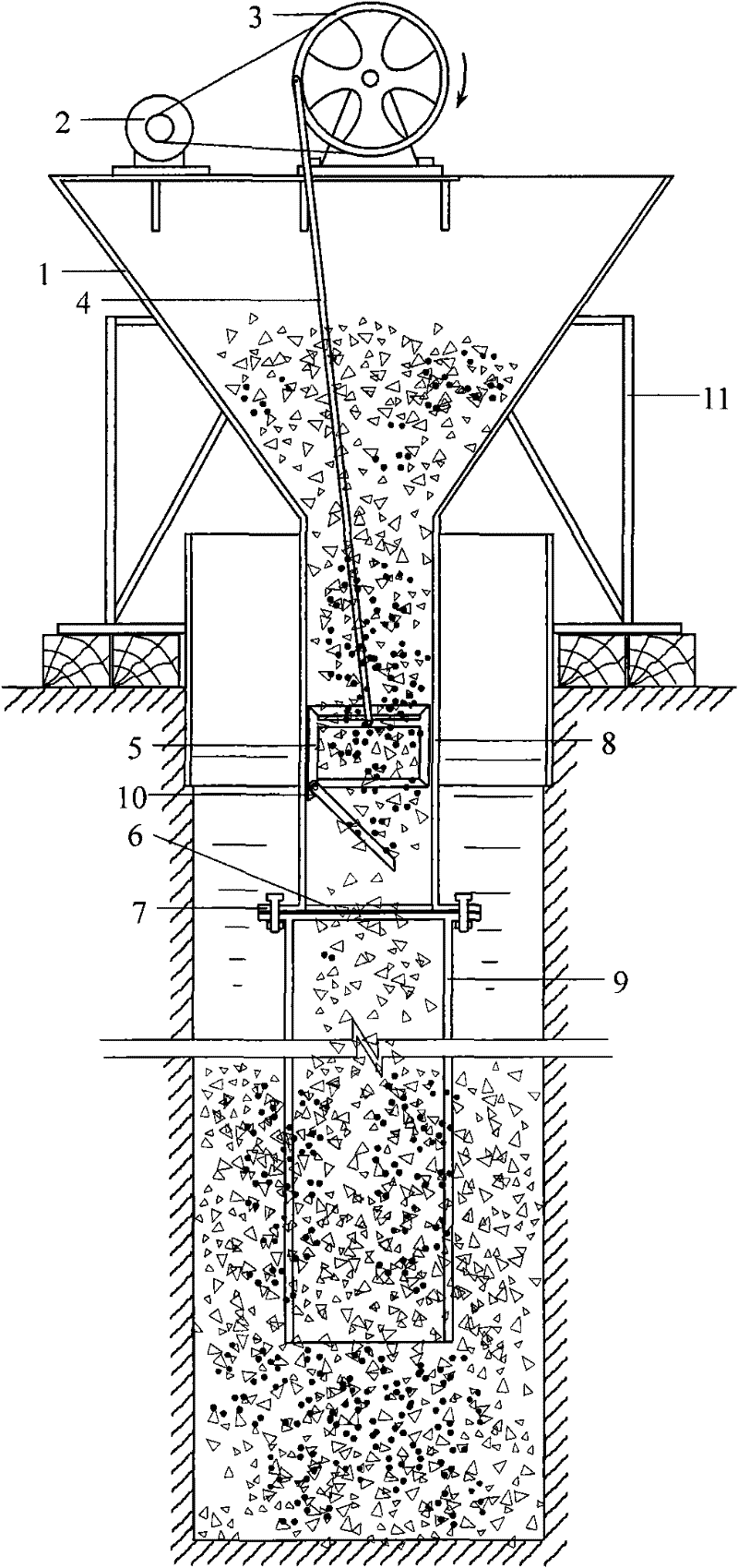
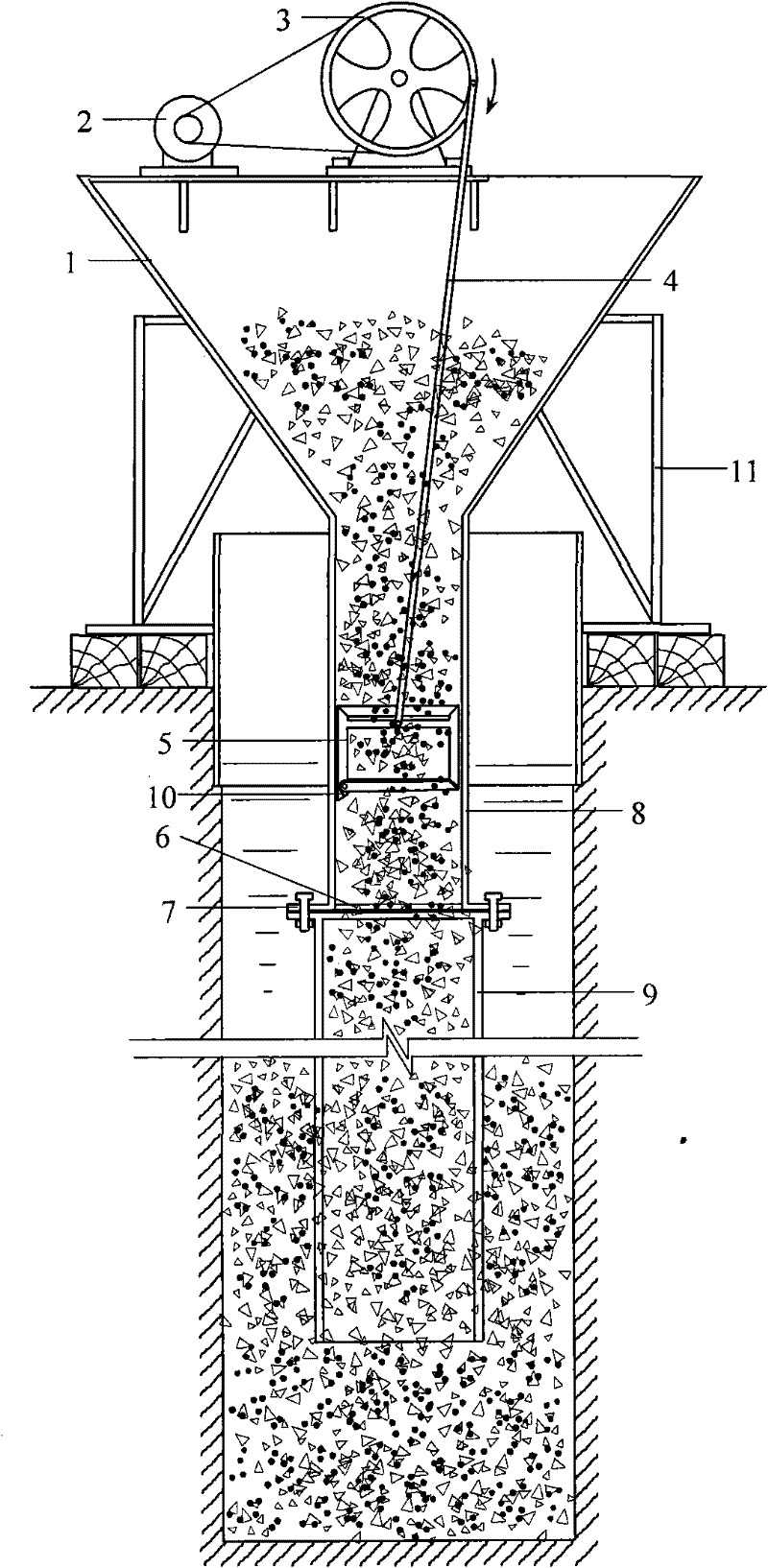
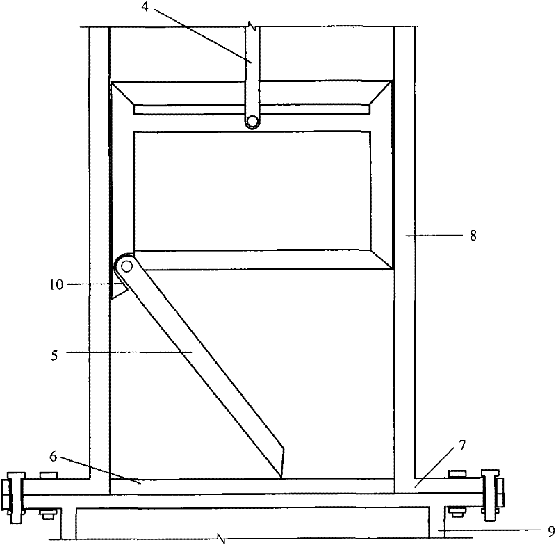
[0022] Depend on Figure 1-4 It can be seen that, at the pile hole after the hole is formed, the hopper 1 is placed on the hopper frame 11, and then the top end of the circular conduit 9 is connected to the square conduit 8 through the variable-section flange 7, and after the circular conduit 9 is connected section by section , down into the pile hole at a distance of 300mm to 500mm from the bottom of the hole. Start the motor 2, drive the driving wheel 3 to rotate, and when the one-way valve plate 5 is driven downward by the pulling and pressing rod 4, it touches the stop rod 6 along the mouth of the square conduit 8, and moves to the square conduit 8 along with the one-way valve plate 5 At the bottom, the stop rod 6 impels the one-way valve plate 5 to close completely, and at this moment, the motor 2 is turned off immediately. According to the pre-calculated result...


PUM


Abstract

The invention belongs to the field of building construction, and relates to a compulsory pouring device and a construction method of bored pile underwater concrete. The device consists of a hopper and conduits and is characterized in that the hopper is provided with an electric motor which is connected with a driving wheel, a square conduit is arranged under the hopper, a one-way valve plate is arranged in the conduit, the driving wheel is connected with the one-way valve plate with a limit support edge via a pull and press rod, the lower end of the square conduit is provided with a stop lever, and the lower end of the square conduit is connected with a circular conduit via a variable cross section flange. When the connection point of the driving wheel and the pull and press rod is rotated to the lowest position, the valve plate is just totally abutted to the position of the stop lever of the edge mouth at the bottom end of the square conduit. The root part of the one-way valve plateis provided with a limit support edge to support the valve plate so as to make the valve plate maintain a certain inclination angle for sagging. The invention greatly reduces concrete slump and can be suitable for concrete with various slumps, thereby reducing material waste, and because compulsory pouring technology is used, the problem that the concrete does not fall easily is solved.

Description

Technical field: [0001] The invention relates to the field of building construction, in particular to forced pouring equipment and a construction method for underwater concrete of cast-in-place piles. technical background: [0002] In the field of building construction, during the construction of cast-in-situ piles, if the soil quality of the cast-in-situ piles is poor and mud retaining walls are used, or the groundwater in the piles is rich, underwater concrete pouring technology is usually used. In order to prevent the concrete in the conduit from falling easily during the pouring process, high slump concrete (generally 140mm-190mm, different slump corresponding to gravel with different particle sizes) is usually used, but the diameter of the conduit, pile Influenced by many factors such as the specific gravity of the inner mud retaining wall and the embedment of the end of the conduit, the problem that the concrete in the conduit is not easy to fall still often occurs. ...

Claims


Application Information

Patent Timeline
Patent Type & Authority Patents(China)
IPC IPC(8): E02D15/06E02D5/38
Inventor 魏勇刘显全矫贵峰
Owner DALIAN AERBIN GROUP
Learn More