System for making polysilicon with assistance of hydrogen plasmas and method therefor
A plasma and polysilicon technology, applied in chemical instruments and methods, polycrystalline material growth, silicon, etc., can solve the problems of low thermal cracking efficiency, complex tail gas components, and high separation costs, so as to reduce energy consumption and shorten reaction deposition time , the effect of reducing the reaction temperature
- Summary
- Abstract
- Description
- Claims
- Application Information
AI Technical Summary
Problems solved by technology
Method used
Image

Examples
Embodiment 1
[0032] 1) A high-purity silicon core rod with a resistivity of 20Ω·cm is used.
[0033] 2) The ICP generating device used has a frequency of 40.68MHz and a power of 100kW.
[0034] 3) The air pressure in the plasma generator and the reduction furnace is controlled at 0.95 bar.
[0035] 4) The raw material gas is a gas mixture of dichlorosilane and silicon tetrachloride with a volume ratio of 1:2.
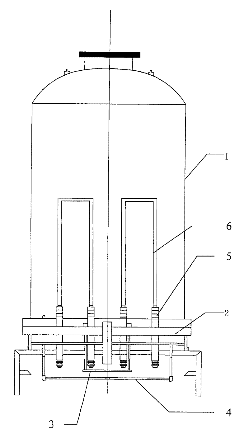
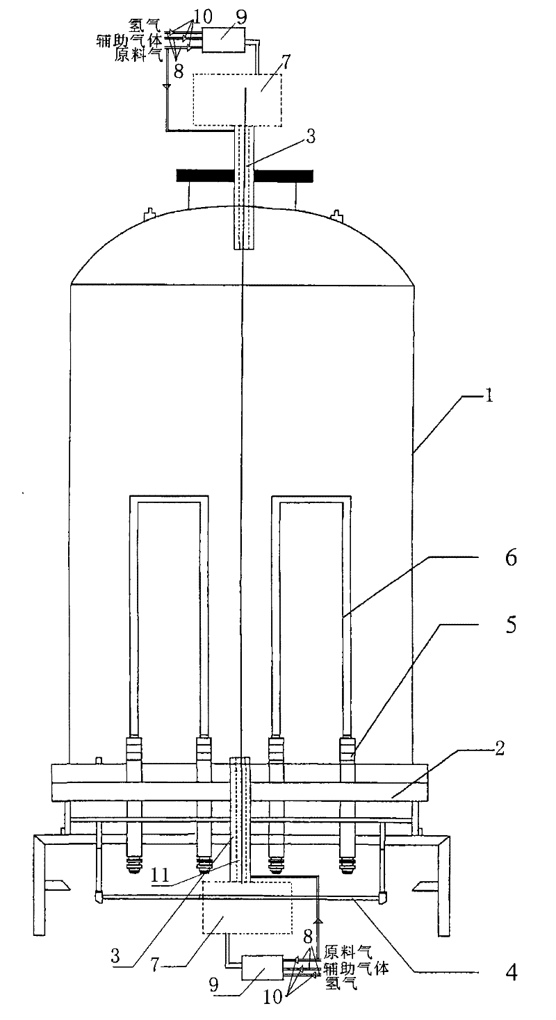
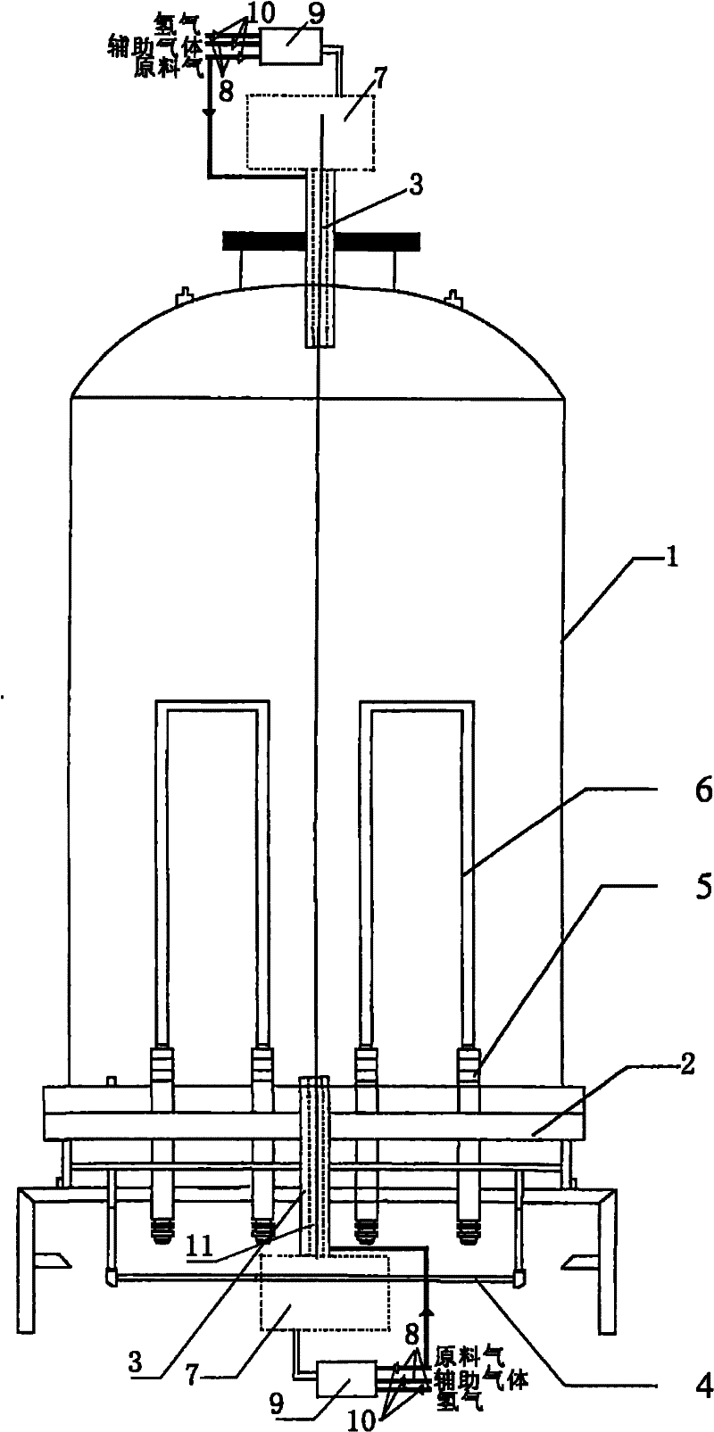
[0036] 5) Connect the above-mentioned silicon core to the electrodes of the chassis in the reduction furnace structure of the present invention. When starting the furnace, first pass through the plasma transformed by mixing hydrogen and auxiliary gas to heat up the silicon core to about 400 ° C. Then apply a voltage to the electrode to form a current in the silicon core, and continue to heat up to 600°C, then gradually cut off the auxiliary gas feed and mix the raw gas with hydrogen through a gas mixer before passing it into the plasma generator. The hydrogen flow rate is controlled...
Embodiment 2
[0038] 1) A high-purity silicon core rod with a resistivity of 50Ω·cm is used.
[0039] 2) The ICP generating device used has a frequency of 40.68MHz and a power of 100kW.
[0040] 3) The air pressure in the plasma generator and the reduction furnace is controlled at 0.95 bar.
[0041] 4) The raw material gas is a gas mixture of dichlorosilane and silicon tetrachloride with a volume ratio of 1:5.
[0042] 5) Connect the above-mentioned silicon core to the electrode of the chassis in the reduction furnace structure of the present invention. When starting the furnace, first pass through the plasma transformed by mixing hydrogen and auxiliary gas to heat up the silicon core to about 500 ° C. Then load current on the electrodes and continue to heat up to 700°C. The hydrogen flow rate was controlled to be 40 cubic meters per hour, and then deposited for 100 hours to obtain silicon rods with a diameter of 120 mm.
Embodiment 3
[0044] 1) A high-purity silicon core rod with a resistivity of 70Ω·cm is used.
[0045] 2) The ICP generating device used has a frequency of 40.68MHz and a power of 100kW.
[0046] 3) The air pressure in the plasma generator and the reduction furnace is controlled at 0.95 bar.
[0047] 4) The raw material gas is a gas mixture with a volume ratio of dichlorosilane and silicon tetrachloride of 1:8.
[0048] 5) Connect the above-mentioned silicon core to the electrode of the bottom plate in the reduction furnace structure of the present invention, and when starting the furnace, first pass through the plasma converted from the mixture of hydrogen and auxiliary gas to heat up the silicon core to about 600°C, And continue to heat up to 800 ° C, and then feed the raw material gas. The hydrogen flow rate was controlled to be 30 cubic meters per hour, and then deposited for 100 hours to obtain silicon rods with a diameter of 100 mm.
PUM
| Property | Measurement | Unit |
|---|---|---|
| electrical resistivity | aaaaa | aaaaa |
| diameter | aaaaa | aaaaa |
| diameter | aaaaa | aaaaa |
Abstract
Description
Claims
Application Information
 - Generate Ideas
- Intellectual Property
- Life Sciences
- Materials
- Tech Scout
- Unparalleled Data Quality
- Higher Quality Content
- 60% Fewer Hallucinations
Browse by: Latest US Patents, China's latest patents, Technical Efficacy Thesaurus, Application Domain, Technology Topic, Popular Technical Reports.
© 2025 PatSnap. All rights reserved.Legal|Privacy policy|Modern Slavery Act Transparency Statement|Sitemap|About US| Contact US: help@patsnap.com