
Antenna structure of digital television and manufacturing method thereof

An antenna structure and digital TV technology, which is applied in the direction of antenna, resonant antenna, radiation element structure, etc., can solve the problems of easy bending, discount of moving force, and lack of design sense of the product, and achieve the reduction of antenna size and good reception characteristics Effect

Inactive Publication Date: 2010-06-23
INPAQ TECH
View PDF3 Cites 2 Cited by
  • Summary
  • Abstract
  • Description
  • Claims
  • Application Information

AI Technical Summary

Problems solved by technology

[0004] However, with the development of thinner mobile electronic products, the manufacturing technology of the receiving antenna has also encountered bottlenecks. For example, the rod-type antenna occupies a considerable size in volume, and the user must push and pull the rod-type antenna to get the best performance. poor viewing quality, causing inconvenience to users; more worried about the rod-type antenna has the disadvantage of low structural strength and easy bending; on the other hand, the use of an external antenna to receive signals greatly reduces the mobility of mobile electronic products, and The product does not have an overall sense of design

Method used


Image

  • Antenna structure of digital television and manufacturing method thereof
  • Antenna structure of digital television and manufacturing method thereof
  • Antenna structure of digital television and manufacturing method thereof

Examples


Embodiment Construction

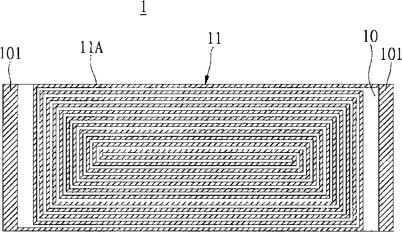
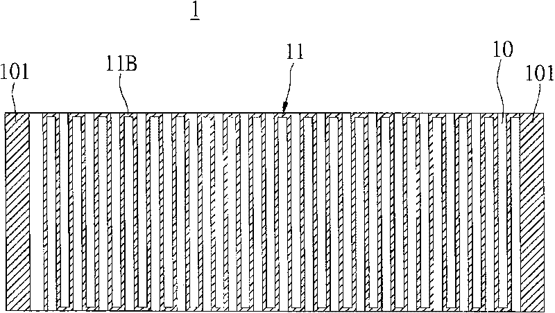
[0024] First, see Figure 1 to Figure 1A As shown, the present invention proposes a digital TV antenna structure 1, which includes: a ceramic substrate 10 and a radiation structure 11; wherein the ceramic substrate 10 has the characteristics of a high dielectric constant, so that the digital TV antenna structure 1 Achieve the effect of miniaturization. The ceramic substrate 10 has a first surface and a second surface opposite to each other, and a radiation structure 11 is formed on the two surfaces. Then, the ceramic substrate 10 and the radiation structure 11 constitute the aforementioned miniaturized digital TV antenna structure 1 .

[0025] figure 1 To show the schematic view of the upper surface (ie, the first surface) of the digital TV antenna structure 1 of the present invention, a first metal microstrip line 11A is arranged in a first pattern on the upper surface of the ceramic substrate 10 . In this specific embodiment, the ceramic substrate 10 is made of aluminum ox...


PUM


Abstract

The invention relates to an antenna structure of a digital television and a manufacturing method thereof. The antenna structure of the digital television comprises: a ceramic substrate having a first surface and a second surface which are opposite; and a radiation structure that is formed on the ceramic substrate and comprises a first metal microstrip line formed on the first surface and a second metal microstrip line formed on the second surface. Accordingly, the invention achieves the function of reducing the antenna size by using the high dielectric constant of the ceramic substrate.

Description

technical field [0001] The invention relates to a digital TV antenna structure and a manufacturing method thereof, in particular to a chip-type miniaturized digital TV antenna structure and a manufacturing method thereof. Background technique [0002] As the development of information technology tends to be thinner and smaller, especially notebook computers, mobile communication products, digital cameras, etc. have gradually become indispensable mobile devices for modern people, in order to be suitable for the characteristics of high space density of mobile device bodies, The demand for each module is not only to maintain high performance and stable quality; how to reduce the module space but still maintain high-quality features, and even improve better data transmission performance and signal quality has become an important issue for manufacturers. [0003] The application of mobile multimedia devices is increasing day by day, such as the promotion and popularization of dig...

Claims


Application Information

Patent Timeline
Patent Type & Authority Applications(China)
IPC IPC(8): H01Q1/22H01Q1/38H01Q13/08H01Q9/30H05K3/12
Inventor 陈志铭赖志豪吴明怡李姿凤
Owner INPAQ TECH
Learn More