Power-on reset control circuit and operation method thereof

A technology for turning on the power supply and controlling the circuit, which is applied in the direction of electronic switches, data processing power supplies, measuring devices, etc., and can solve the problem that the reset signal is not generated.

Active Publication Date: 2011-12-14
HOLTEK SEMICON
View PDF0 Cites 0 Cited by
  • Summary
  • Abstract
  • Description
  • Claims
  • Application Information

AI Technical Summary

Problems solved by technology

It is mentioned in this patent that when the value comparison result needs to be reset, the implementation of the circuit structure is to reuse the value of the judgment counter to determine the reset cycle, but the value of the counter may be the predetermined value from the beginning, so There will be doubts that the reset signal is not generated

Method used


Image

  • Power-on reset control circuit and operation method thereof
  • Power-on reset control circuit and operation method thereof
  • Power-on reset control circuit and operation method thereof

Examples


Embodiment Construction

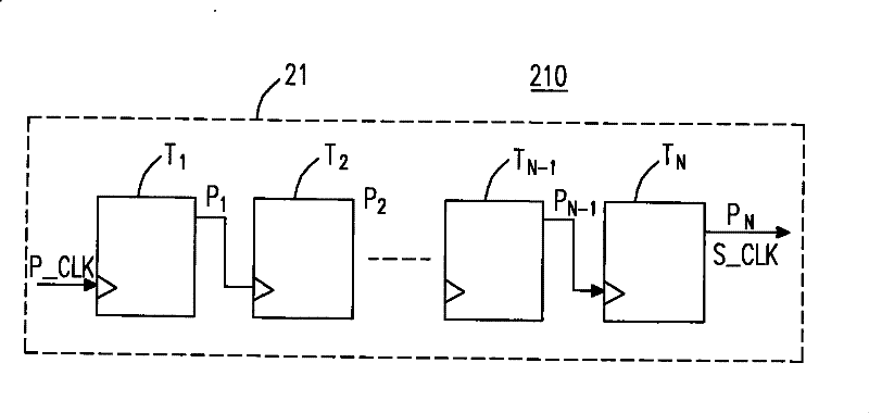
[0025] The circuit design concept is based on the idea that the necessary condition for the chip (IC) to work is that the clock must start to oscillate. The RC oscillator or crystal (Crystal) oscillator is used to start oscillating the initial oscillation signal related to the voltage, and the frequency divider is shifted to The bit register sends a stable shift clock signal, and the level that starts to shift the register is sequentially shifted and supplemented in a first-in-first-out manner, and the output of the last stage of the shift register is used as a power-on reset signal.

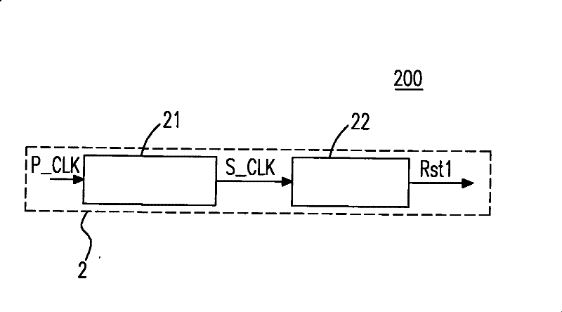
[0026] Please refer to FIG. 2( a ), which is a structural diagram of a digital power-on-reset generating circuit 2 . The digital power-on-reset generating circuit 2 includes a frequency divider 21 and a first shift register 22 . When the first voltage rises to the starting voltage, the oscillator (not shown) starts to generate the oscillation signal P_CLK, the frequency divider 21 receives the os...


PUM


Abstract

The invention discloses a power-on reset control circuit, which includes: a frequency divider and a shift register, the clock input end of the shift register is electrically connected to the output end of the frequency divider, wherein when the power is turned on, the reset When the control circuit is applied with a first voltage: the frequency divider generates a frequency division signal at the output terminal of the frequency divider through the initial oscillation signal related to the voltage, and the data input terminal of the shift register receives a preset level, and output a power-on reset signal in a first-in-first-out operation. The power-on-reset signal is used to assist the main power-on-reset signal.

Description

technical field [0001] The invention relates to a power-on reset control circuit and an operation method thereof, which are especially used for electronic system reset. Background technique [0002] Generally speaking, when an electronic product starts to be powered on, its internal electronic circuit system must be reset before it can start to work normally. The power on reset method is generally that an analog RC circuit generates a reset signal to reset the electronic system, but the reset signal may not be generated. [0003] Taking the chip (IC) as an example, at time t1, when the external power supply begins to drop to the point where the chip (IC) cannot work, but does not drop to 0V, after a period of time, the power supply returns to VDD, and the power supply changes as follows: figure 1 As shown, in this case, poor power on reset (Power on Reset) often occurs, so that the chip (IC) may not work properly or even completely fail to work after it has not passed the i...

Claims


Application Information

Patent Timeline
IPC IPC(8): G06F1/24G06F1/26H03K17/22
Inventor 胡闵雄林春安
Owner HOLTEK SEMICON
Why Eureka
Try Eureka