Fiber collimator

A fiber collimator and fiber head technology, which is applied in optics, instruments, optical components, etc., can solve problems such as obstacles to the development of fully automatic and semi-automatic equipment, and achieve the effect of eliminating the deflection angle

Inactive Publication Date: 2010-06-23
深圳市天阳谷科技发展有限公司
View PDF3 Cites 7 Cited by
  • Summary
  • Abstract
  • Description
  • Claims
  • Application Information

AI Technical Summary

Problems solved by technology

This also creates a huge obstacle for the development of fully automatic and semi-automatic equipment in the future.

Method used


Image

  • Fiber collimator
  • Fiber collimator
  • Fiber collimator

Examples


Embodiment Construction

[0021] In order to make the object, technical solution and advantages of the present invention clearer, the present invention will be further described in detail below in conjunction with the accompanying drawings and embodiments.

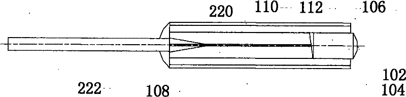
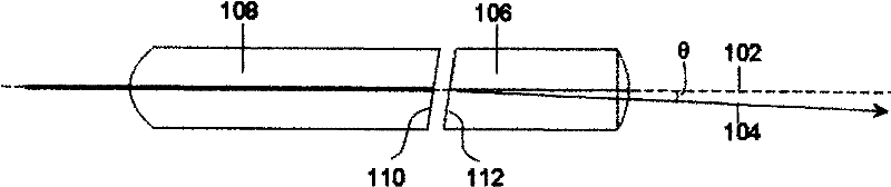
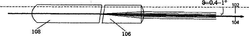
[0022] In this example, see figure 1 It can be seen that the fiber collimator includes at least one precisely positioned fiber head 108 and a collimator lens 106, a sleeve 220 for fixing the fiber head 108 and the collimator lens 106, the fiber head 108 and the collimator installed in the sleeve 220 The straight lens 106 is placed end to end in a straight line, the front end face 110 of the optical fiber head 108 is docked with the rear end face 112 of the collimator lens 106, the collimator lens 106 has an optical axis 104, and the sleeve 220 has its own central axis 102 .

[0023] The rear end face 112 of the collimating lens 106 is perpendicular to the central axis 102 of the sleeve pipe 220, and the distance between the rear end face 112 of th...


PUM


Abstract

The invention discloses a fiber collimator, which comprises at least one fiber head for accurate positioning and a collimation lens, and a casing for fixing the fiber head and the collimation lens. The fiber head and the collimation lens which are arranged in the casing are aligned end to end; the front end face of the fiber head is in butt joint with the rear end face of the collimation lens; the collimation lens is provided with an optic axis; and the casing is provided with an inherent central axis. The fiber collimator is characterized in that: the rear end face of the collimation lens is vertical to the central axis of the casing; and the distance between the rear end face of the collimation lens and the front end face of the fiber head is equal to the distance between a focal point of the collimation lens and the rear end face of the collimation lens. The surfaces of the fiber head and the collimation lens are subjected to special designs so as to achieve the effects of removing emergent lights or receiving the deflection angle of the light, which also can create huge benefits and advantages.

Description

【Technical field】 [0001] The invention relates to the fields of optical communication and optoelectronics, in particular to an optical fiber collimator whose optical axis is parallel to the central axis of an external fixing part. 【Background technique】 [0002] The fiber collimator Collimator is composed of a fiber optic head, a collimator lens for precise positioning, and then coated with some glass sleeves or metal sleeves. The light is injected into the collimating lens by the fiber head, so the front end of the fiber head faces the rear end face of the collimating lens. The optical fiber head is made by inserting the optical fiber into a capillary whose inner diameter closely matches the outer diameter of the optical fiber, and then grinding the end face after fixing. The material of capillary can be glass, pottery, metal, plastic. The main function of the sleeve is to accurately locate and fix the relative position between the fiber optic head and the lens. The inne...

Claims


Application Information

Patent Timeline
IPC IPC(8): G02B27/30G02B7/02
Inventor 黄燕平
Owner 深圳市天阳谷科技发展有限公司
Why Eureka
Try Eureka