
Phase hunting detection method for permanent magnet planar motor adopting switch Hall array

A permanent magnet plane and detection method technology, applied in the direction of phase sequence/synchronous indication, etc., can solve the problems that the phase relationship between the coil and the permanent magnet array cannot be determined, and the commutation point of the drive unit coil cannot be determined, etc., achieving strong anti-interference ability, No noise accumulation, simple circuit processing effect

Active Publication Date: 2010-06-23
TSINGHUA UNIV
View PDF0 Cites 9 Cited by
  • Summary
  • Abstract
  • Description
  • Claims
  • Application Information

AI Technical Summary

Problems solved by technology

The relative position measurement of the drive unit and the permanent magnet array generally uses an incremental position sensor such as a grating ruler, so that the commutation point of the drive unit coil (the position of the coil and the permanent magnet array corresponding to the current zero crossing point in the coil) cannot be determined, that is, Unable to determine the phase relationship of the coil and the initial position of the permanent magnet array

Method used


Image

  • Phase hunting detection method for permanent magnet planar motor adopting switch Hall array
  • Phase hunting detection method for permanent magnet planar motor adopting switch Hall array
  • Phase hunting detection method for permanent magnet planar motor adopting switch Hall array

Examples


Embodiment Construction

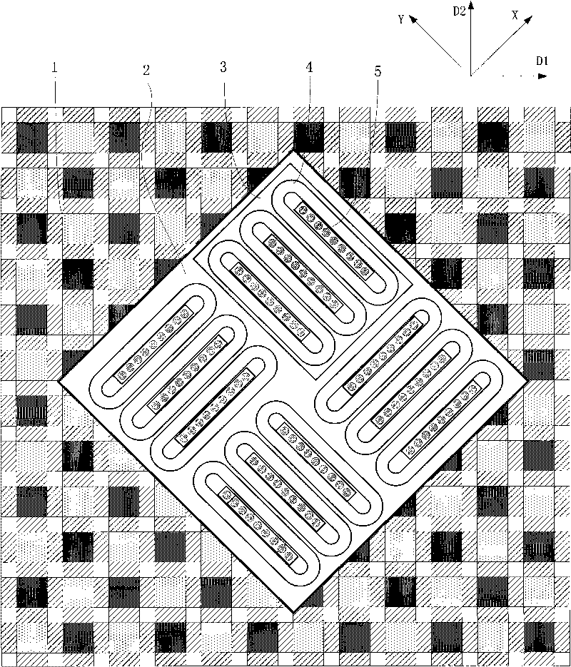
[0025] The present invention provides a permanent magnet planar motor phase-finding detection method using a switch Hall array. The permanent magnet planar motor contains a permanent magnet array and a coil array. The coil array is composed of more than two drive units, each A drive unit is made up of more than two coils, it is characterized in that the method comprises the steps:

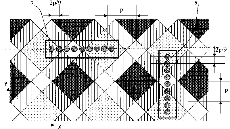
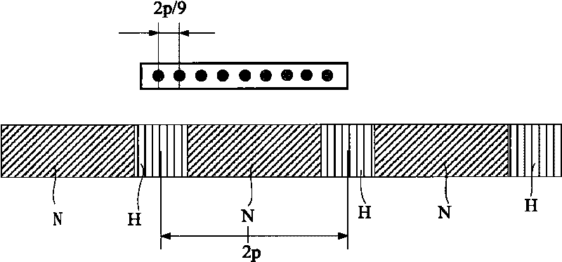
[0026] a. Each coil corresponds to a Hall array, and the Hall array is placed perpendicular to the horizontal output direction of the drive unit where the coil is located. The Hall array is composed of M (M≥3 and odd) switch Hall sensors, The switch hall sensors are distributed at equal intervals within even multiples of the pole distance;

[0027] b. The switch hall sensor is placed in parallel with the permanent magnet array, which is used to measure the magnetic flux density component perpendicular to the moving direction of the planar motor; if the magnetic flux density measured by the switch h...


PUM


Abstract

The invention relates to a phase hunting detection method for a permanent magnet planar motor adopting a switch Hall array. The method is characterized in that: a Hall array consists of M (M is an odd number and more than or equal to 3) switch Hall sensors, wherein the Hall array is vertical to the horizontal force direction of a driving unit where the coil is positioned; the switch Hall sensors in the Hall array are arranged at equal intervals which is an even number times the pole pitch, are parallel to a permanent magnet array and used for measuring the component of the magnetic flux density in the direction vertical to the movement direction of the planar motor. All the switch Hall sensor signals in the Hall array are added up and then an judgment is made to determine whether the sum is greater than M / 2 so as to acquire an output signal 0 or 1; the output signal is kept unchanged when the Hall array moves in the direction vertical to the horizontal thrust direction of the corresponding coil; the output signals 0 and 1 are alternated when the Hall array moves in the horizontal thrust direction of the corresponding coil; and the current zero-crossing point (phase shifting point) in the driving coil is determined. The method changes the phase hunting detection of the permanent magnet planar motor in two dimension into superposition of two one-dimensional phase hunting detections to realize the planar phase hunting detection.

Description

technical field [0001] The invention relates to a phase-finding method for a permanent magnet planar motor, in particular to a measurement method for determining a coil current commutation point of a permanent magnet planar motor by using a switch Hall array. Background technique [0002] With the rapid development of advanced manufacturing industry, high-precision positioning platform technology has been in-depth research and development, and has broad application prospects in the semiconductor industry, micro-stereolithography, nano-workbench, high-precision plotter and other fields, among which the most important Its application is a high-precision lithography positioning platform in the semiconductor industry. Modern precision and ultra-precision machining equipment has a wave-cutting demand for high-response, high-speed, and high-precision planar drive devices. The original planar driving device was realized by two direct-driven linear motors, using a stacked driving s...

Claims


Application Information

Patent Timeline
IPC IPC(8): G01R29/18
Inventor 张鸣朱煜徐云龙汪劲松胡金春尹文生杨开明徐登峰段广洪尉鹏
Owner TSINGHUA UNIV
Learn More