Vertical remote cold and hot energy transporting system
A vertical and long-distance technology, applied in the field of high-efficiency energy-saving system devices, to achieve the effects of convenient operation, flexible adjustment and control methods, and small diameter of transportation pipelines
- Summary
- Abstract
- Description
- Claims
- Application Information
AI Technical Summary
Problems solved by technology
Method used
Image

Examples
Embodiment 1
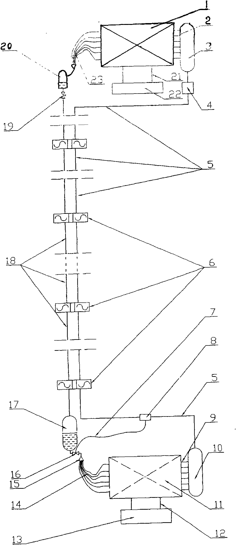
[0026] Embodiment 1: each of the condenser 1 and the evaporator 11 of this embodiment is one, which is a system for one supply; The equipment 13 for environmental heat exchange constitutes the heat exchange subsystem of the evaporator, which continuously provides heat for the evaporation of the liquid working medium in the evaporator, and at the same time completes the task of cooling the position of the evaporator; the condenser 1, the liquid receiver 20. Regulating valve 19, liquid working medium main pipe 18, n (1≤n≤50) gravity potential energy recovery compressors 6, step-down gas-liquid separator 17, expansion valve 16, liquid separator 15, liquid equalizing pipe 14. Evaporator 11, evaporator gas collection main pipe 9, gas working medium transport main pipe 10, gas compressor 4, condenser gas distribution main pipe 3 and gas equalization pipe 2 constitute the heat pump (or heat pipe) working medium internal circulation sub-pipe The system continuously transports the heat...
Embodiment 2
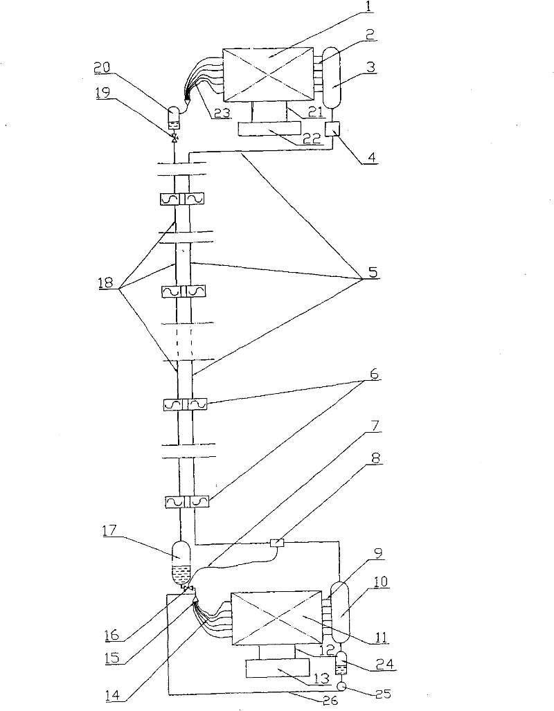
[0028] Embodiment 2: The evaporator heat exchange subsystem and the condenser heat exchange subsystem of this embodiment are the same as in Embodiment 1, and the composition and working process of the heat pump (or heat pipe) working medium internal circulation subsystem are also basically the same as in Embodiment 1. , but a small circulation system of liquid working medium composed of a liquid reservoir 24, a solution pump 25, and a liquid working medium supply pipe 26 is installed on the side of the evaporator. This small circulation system can improve the phase change heat process in the evaporator , improve heat transfer efficiency.
[0029] In this embodiment, each component is first attached figure 2 As shown in the installation, vacuumize the internal circulation subsystem of the heat pump (or heat pipe) and fill it with an appropriate amount of circulating fluid, then adjust the regulating valve to an appropriate opening, and start the heat exchange subsystem of the ...
Embodiment 3
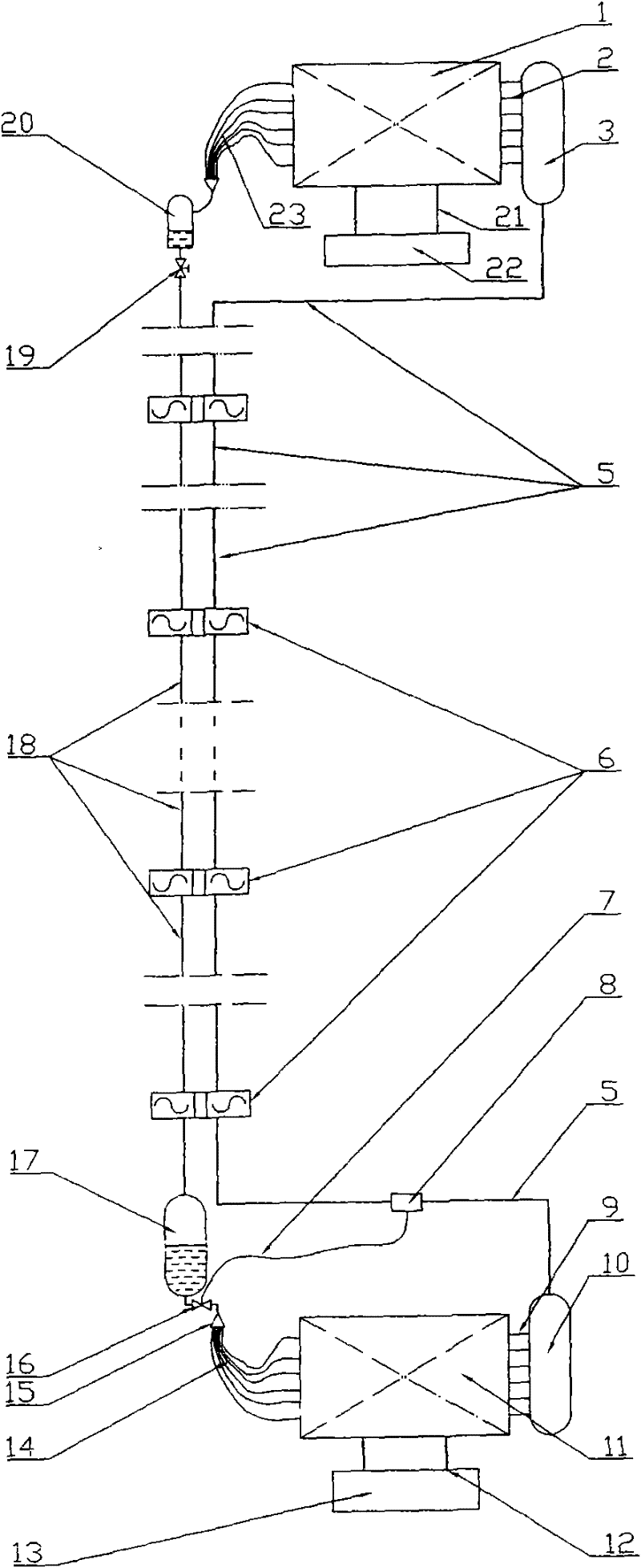
[0030] Embodiment 3: The heat exchange subsystem of the evaporator and the heat exchange subsystem of the condenser in this embodiment are the same as in Embodiment 1, and the basic composition of the internal circulation subsystem of the heat pipe is similar to that of Embodiment 1, except that there is no gas compressor. Therefore, only the heat pipe circulation process can be realized.
[0031] In this embodiment, each component is first attached image 3 As shown in the installation, vacuumize the internal circulation subsystem of the heat pipe working medium and fill it with an appropriate amount of circulating working medium, then adjust the regulating valve to an appropriate opening, start the evaporator heat exchange subsystem and the condenser heat exchange subsystem, and then Start operation; after a certain period of time, the heat exchange subsystem of the evaporator, the internal circulation subsystem of the heat pipe and the heat exchange subsystem of the condens...
PUM
 Abstract
Description
Claims
Application Information
 - Generate Ideas
- Intellectual Property
- Life Sciences
- Materials
- Tech Scout
- Unparalleled Data Quality
- Higher Quality Content
- 60% Fewer Hallucinations
Browse by: Latest US Patents, China's latest patents, Technical Efficacy Thesaurus, Application Domain, Technology Topic, Popular Technical Reports.
© 2025 PatSnap. All rights reserved.Legal|Privacy policy|Modern Slavery Act Transparency Statement|Sitemap|About US| Contact US: help@patsnap.com