Transmission method of tractor and permanent-magnet synchronous tractor
A traction machine and rotating shaft technology, applied in the field of traction machines, can solve the problems of difficulty in ensuring the air gap of the stator and rotor, reduce the performance of the traction machine, destroy the concentricity of the stator and the rotor, etc., so as to reduce the performance loss of the motor, reduce the bending strain, The effect of improving the processing yield
- Summary
- Abstract
- Description
- Claims
- Application Information
AI Technical Summary
Problems solved by technology
Method used
Image
Examples
Embodiment 1
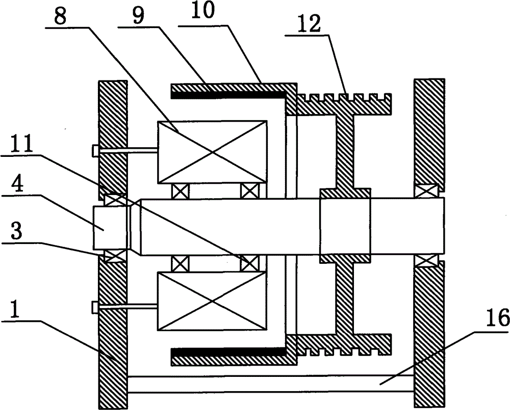
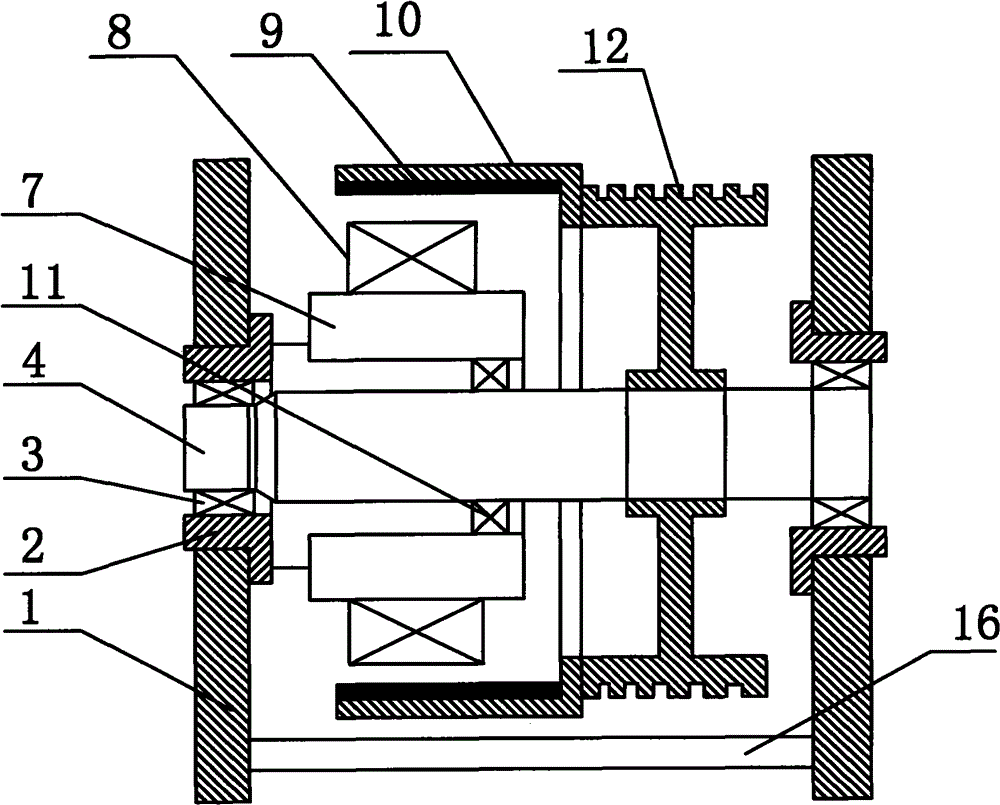
[0020] A transmission method for a permanent magnet synchronous traction machine, characterized in that: a stator is positioned by a bearing on a rotating shaft, and a coaxially installed rotor is driven. The stator is positioned on the rotating shaft through the iron core seat and the bearing on the rotating shaft, or directly positioned on the rotating shaft through the bearing on the rotating shaft, so as to ensure the concentricity of the rotor and the stator. The connecting end of the iron core seat is connected with the support plate supporting the rotating shaft through pins or keys or with the bearing seat on the support plate for installing the load bearing, which limits the freedom of the torque direction of the iron core seat, but allows There is a certain degree of rotation in the direction of the load on the pulley. The core base or the stator is supported by the load bearing on the supporting plate and the supporting bearing on the rotating shaft, or by more than...
Embodiment 2
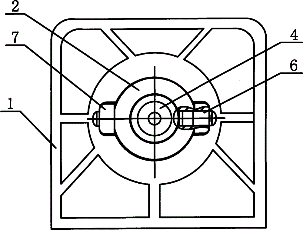
[0024] Transmission method is the same as embodiment 1. Another way to realize this method: a permanent magnet synchronous traction machine, constituted as figure 1 with image 3 As shown, it includes a rotating shaft 4, a traction sheave 12 on the rotating shaft 4, a stator 8, a rotor yoke 10 and a permanent magnet 9 fixed on the inside of the rotor yoke 10, and it is characterized in that: the rotor yoke 10 is fixed on the On the traction wheel 12, or as a whole with the traction wheel 12, support plates 1 are respectively provided on both sides of the traction wheel 12, a bearing seat 2 is provided on the support plate 1, and a load bearing 3 is provided in the bearing seat 2 for Support rotating shaft 4, the connecting end that is connected with iron core seat 7 by pin 6 or key on bearing block 2, the other end of iron core seat 7 is fixed on the outer ring of support bearing 11 in rotating shaft 4 middle parts. The stator 8 is installed on the iron core base 7 . The su...
PUM
 Abstract
Description
Claims
Application Information
 - R&D
- Intellectual Property
- Life Sciences
- Materials
- Tech Scout
- Unparalleled Data Quality
- Higher Quality Content
- 60% Fewer Hallucinations
Browse by: Latest US Patents, China's latest patents, Technical Efficacy Thesaurus, Application Domain, Technology Topic, Popular Technical Reports.
© 2025 PatSnap. All rights reserved.Legal|Privacy policy|Modern Slavery Act Transparency Statement|Sitemap|About US| Contact US: help@patsnap.com


