
Homogenizer

A homogenizer and unified technology, applied to chemical instruments and methods, emulsification, fluid mixers, etc., can solve the problems of increased energy consumption of power equipment, difficulty in mixing uniformly, increased maintenance costs, etc., to increase the degree of homogenization, Ease of use and improved homogenization efficiency

Inactive Publication Date: 2010-06-23
NANJING HAOYANG CHEM EQUIP
View PDF1 Cites 5 Cited by
  • Summary
  • Abstract
  • Description
  • Claims
  • Application Information

AI Technical Summary

Problems solved by technology

Although some manufacturers have developed some products, most of them use equipment such as installation of stirring systems or use some expensive devices with special properties to make them evenly mixed. However, as we all know, in chemical equipment, power equipment increases energy consumption. At the same time, it also increases the daily maintenance cost
Moreover, with the continuous improvement of the requirements and degree of differentiation, it may be necessary to add the fourth monomer, the fifth monomer, etc., and the current technology is more difficult to achieve the purpose of making it evenly mixed.

Method used


Image

  • Homogenizer
  • Homogenizer
  • Homogenizer

Examples


Embodiment 1

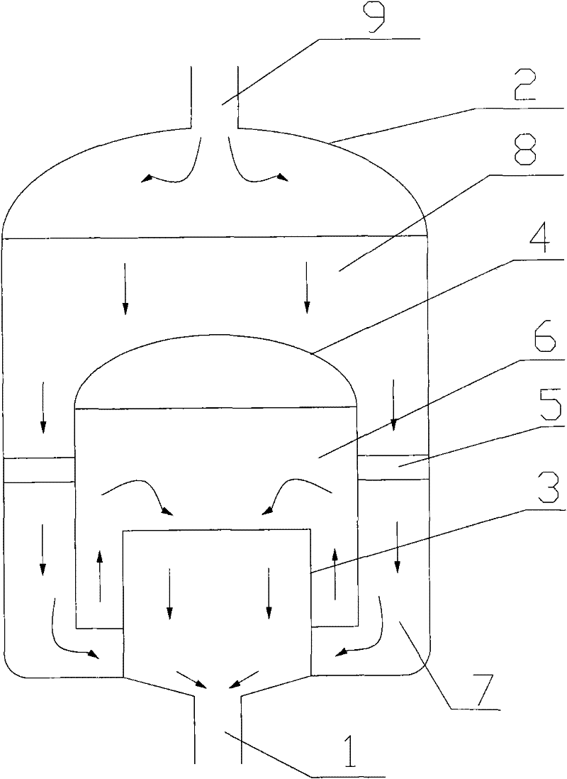
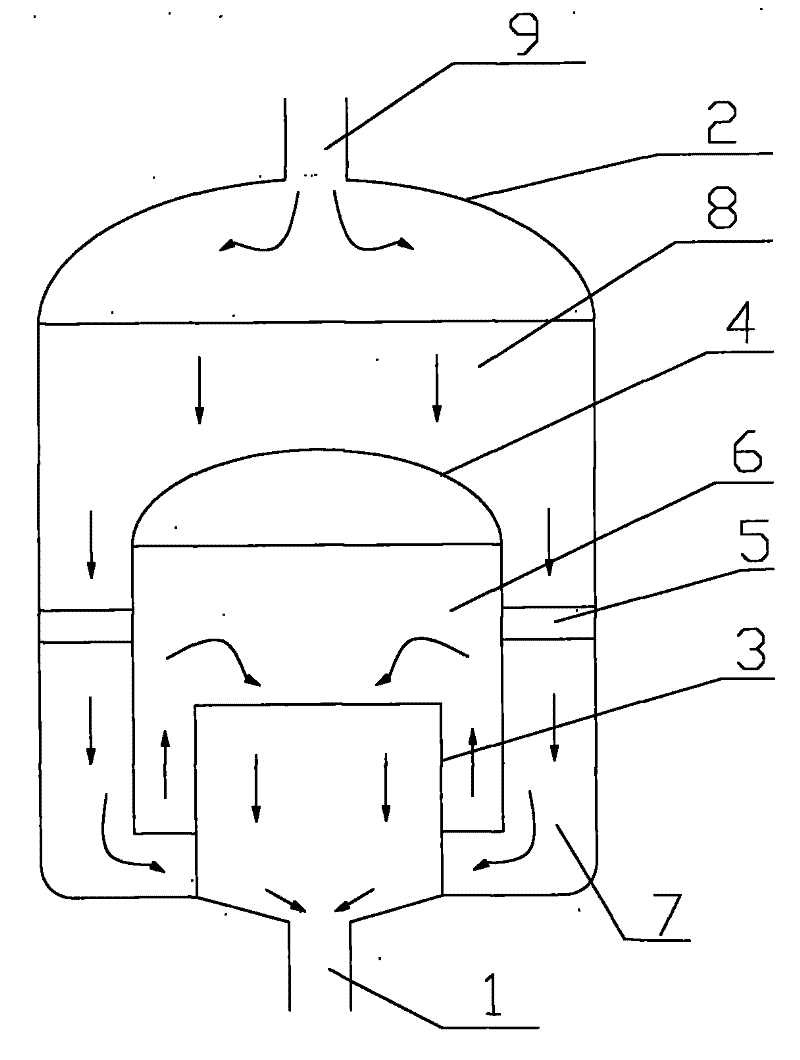
[0033] attached figure 1 As shown, the device has a total of three concentric cylinders, the innermost first cylinder 3 has no cover, and its height is 2 / 3 of the second cylinder 4 with a cover. The second cylinder 4 passes through the fixing bar. Connected with the outermost first cylinder 2, the height of the second cylinder 4 is half of the height of the first cylinder 2, and the distance from the bottom edge of the second cylinder to the bottom of the homogenizer is 1 / 4 of the height of the first cylinder 3 ~1 / 3. The radius of the first cylinder 3 is 2 / 3 of the second cylinder 4 , and the radius of the second cylinder 4 is 2 / 3 of the first cylinder 2 . The mixed material enters the second cylinder 4 through the cavity 7 composed of the first cylinder 2 and the second cylinder 4 in the direction of the arrow according to the direction of the arrow, and the second cylinder 4 is fixed with the first cylinder 2 outside by the fixing strip The material is pushed up by the mat...

Embodiment 2

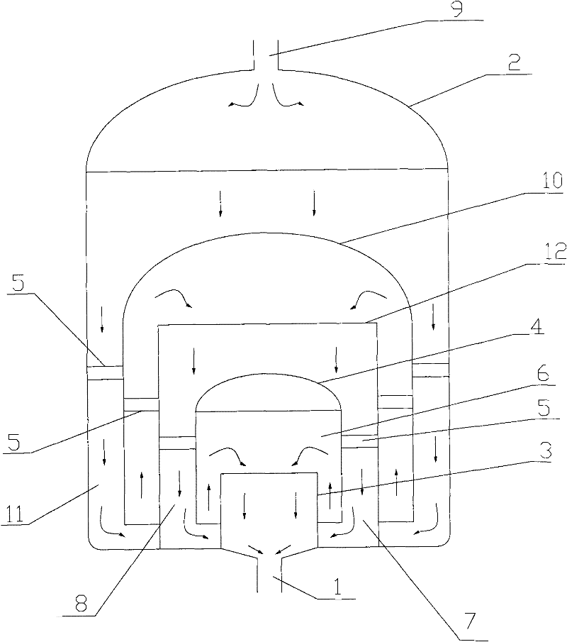
[0035] attached figure 2As shown, the device consists of 5 coaxial cylinders in total, including 3 first cylinders and 2 second cylinders, which are coaxially sleeved with each other. The innermost first cylinder 3 has no cover, its height is 2 / 3 of the covered second cylinder 4, the radius of the first cylinder 3 is 2 / 3 of the second cylinder 4, and the bottom of the second cylinder 4 The height from the edge to the bottom of the homogenizer is 1 / 4 of the height of the first cylinder 3, and the second cylinder 4 is connected to the first cylinder 12 set outside it through the fixing strip 5; the height of the second cylinder 4 is the first 1 / 2 of the height of the cylinder 12, the radius of the second cylinder 4 is 2 / 3 of the first cylinder 12, the top of the first cylinder 12 is open, and the bottom shares a bottom with the homogenizer; the second cylinder with a cover The cylinder 10 is sleeved on the outside of the first cylinder 12, the height of the first cylinder 12 i...


PUM

PropertyMeasurementUnit
angleaaaaaaaaaa
intrinsic viscosityaaaaaaaaaa

Abstract

The invention relates to a homogenizer comprises at least n first cylinders and at least n-1 second cylinders, which are sleeved together at intervals. The inmost cylinders and the outmost cylinders are both first cylinders; the top of the outmost first cylinder is closed and is provided with an opening which is communicated with the outside, and the bottom is provided with an opening which is communicated with the inside of the innermost first cylinder; the tops of other first cylinders are open; all the first cylinders share the bottom of the same homogenizer; the second cylinders are sleeved outside the first cylinders which are adjacent to the second cylinders at intervals; the tops of the second cylinders are open, and the bottoms are closed, thus a space in the homogenizer, where all the first cylinders are communicated with all the second cylinders, is formed; and the first cylinders and the second cylinders are fixed mutually by connecting parts.

Description

technical field [0001] The present invention relates to a homogenizing device for liquid mixing, more specifically, to a homogenizer. Background technique [0002] In recent years, with the gradual increase of differentiated polyester varieties and the continuous development of preparation technology, the market demand for modified polyester products is increasing. However, due to the high crystallinity, high degree of orientation and high Due to the low glass transition temperature and other properties, it is difficult for the dye to diffuse into the PET molecules, and it is difficult to dye. In order to solve the problem of PET dyeing, polyester can be modified mainly from several aspects such as pre-spinning coloring modification, chip blending and spinning modification, and copolymerization modification. [0003] Currently, the third method that is widely used in the market is to add a third monomer for copolymerization modification. Therefore, the rational arrangement...

Claims


Application Information

Patent Timeline
Patent Type & Authority Applications(China)
IPC IPC(8): B01F5/06B01F3/10B01F23/47
Inventor 汪少朋李建成
Owner NANJING HAOYANG CHEM EQUIP
Learn More