Probe pin
A probe and conductive needle technology, applied in the field of probes, can solve the problems of difficulty in ensuring the pull-out strength, decrease in the adhesion between the insulator and the conductive needle, hindering the narrowing of the probe, and achieve higher pull-out strength and buckling strength. improved effect
- Summary
- Abstract
- Description
- Claims
- Application Information
AI Technical Summary
Problems solved by technology
Method used
Image

Examples
no. 1 approach
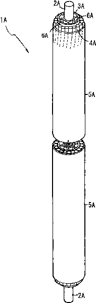
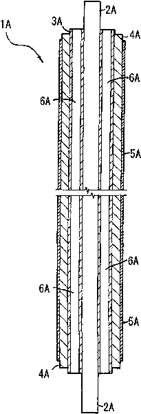
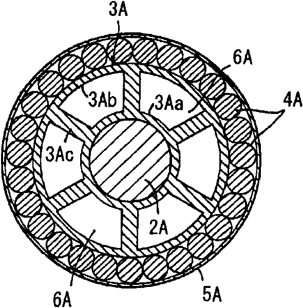
[0088] figure 1 and figure 2 The appearance of the probe 1A according to the first embodiment of the present invention and the cross-sectional view of the probe 1A are respectively shown in . The probe 1A has a conductive needle 2A, an insulator 3A penetrated at the center by the conductive needle 2A, an outer conductor 4A arranged around the outer periphery of the insulator 3A coaxially with the conductive needle 2A, and an insulating sheath covering the outer periphery of the outer conductor 4A. 5A. The probe 1A is formed in an extremely thin wire shape with an axial length of about 20 mm and an outer diameter of about 0.3 mm. The conductive needle 2A is formed of a single-core tungsten wire with a diameter of approximately 0.1 mm, and in this example, the lower end serving as a detection end is formed in a flat shape. The outer conductor 4A is formed by winding more than 20 tinned copper alloy filaments with a diameter of 0.03 mm in a spiral shape. The insulator 3A is ...
no. 2 approach
[0131] Hereinafter, some contents of the second embodiment of the present invention will be described with reference to the drawings. exist Figure 7 ~ Figure 10 In, a probe 1B according to a second embodiment of the present invention is shown, Figure 7 is the perspective view of the appearance of probe 1B, Figure 8 It is the front view of the longitudinal section of probe 1B, Figure 9 is an enlarged front view of the main part of probe 1B, Figure 10 It is a cross-sectional view of probe 1B.
[0132] The probe 1B has a conductive needle 2B, an insulator 3B inserted through the center by the conductive needle 2B, an outer conductor 4B disposed on the outer periphery of the insulator 3B coaxially surrounding the conductive needle 2B, and an insulating sheath covering the outer periphery of the outer conductor 4B. The insulating tape winding layer 5B is formed in an extremely thin wire shape with a length of about 20 mm in the axial direction and an outer diameter of 0.3 ...
no. 3 approach
[0144] exist Figure 12 to Figure 14 In , a probe 1C according to a third embodiment of the present invention is shown. Figure 12 is a perspective view of the appearance of probe 1C, Figure 13 is the longitudinal section front view of probe 1C, Figure 14 It is a cross-sectional top view of probe 1C.
[0145] The probe 1C of this embodiment has a conductive needle 2C, an insulator 3C inserted through the center of the conductive needle 2C, an outer conductor 4C arranged around the outer periphery of the insulator 3C coaxially with the conductive needle 2C, and a metal covering the outer periphery of the outer conductor 4C. An insulating tape wrapping layer 5C as an insulating sheath. The structure other than the insulator 3C is the same as that of the second embodiment.
[0146] The insulator 3C in this embodiment is formed of an insulating resin material such as PFA (tetrafluoroethylene-perfluoroalkyl vinyl ether copolymer), and is formed to have an inner layer body 3Ca...
PUM
 Abstract
Description
Claims
Application Information
 - R&D
- Intellectual Property
- Life Sciences
- Materials
- Tech Scout
- Unparalleled Data Quality
- Higher Quality Content
- 60% Fewer Hallucinations
Browse by: Latest US Patents, China's latest patents, Technical Efficacy Thesaurus, Application Domain, Technology Topic, Popular Technical Reports.
© 2025 PatSnap. All rights reserved.Legal|Privacy policy|Modern Slavery Act Transparency Statement|Sitemap|About US| Contact US: help@patsnap.com