Permanent magnet synchronous motor with interphase uncoupled structure
A permanent magnet synchronous motor, non-coupling technology, applied to synchronous motors with stationary armature and rotating magnets, synchronous machine parts, magnetic circuit shape/style/structure, etc., can solve the problem of large stator iron loss, etc. Achieve the effects of less coils, simple processing technology, and reduced eddy current loss
- Summary
- Abstract
- Description
- Claims
- Application Information
AI Technical Summary
Problems solved by technology
Method used
Image
Examples
specific Embodiment approach 1
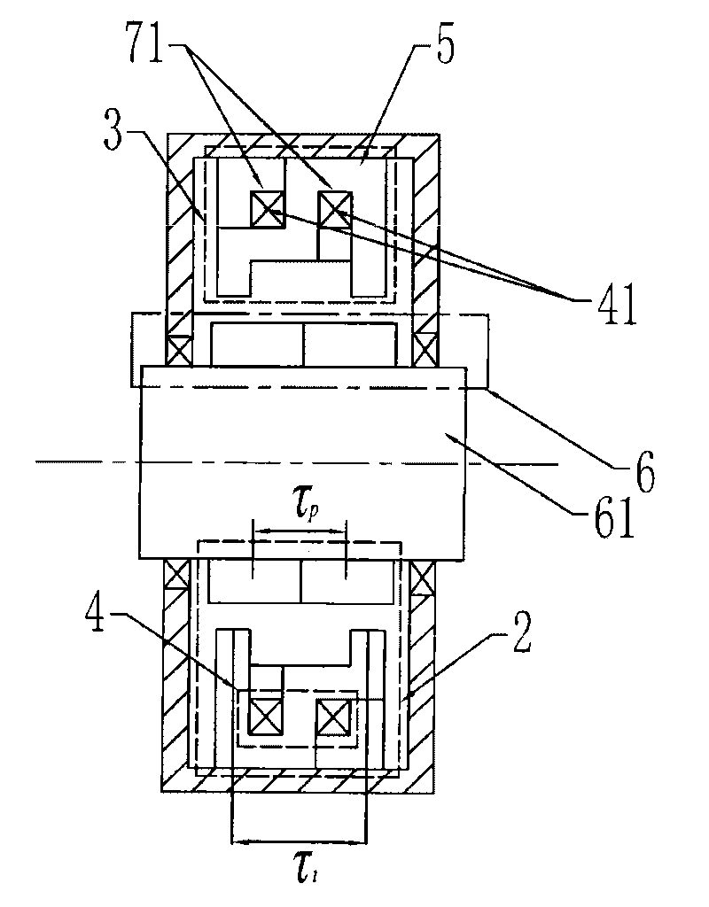
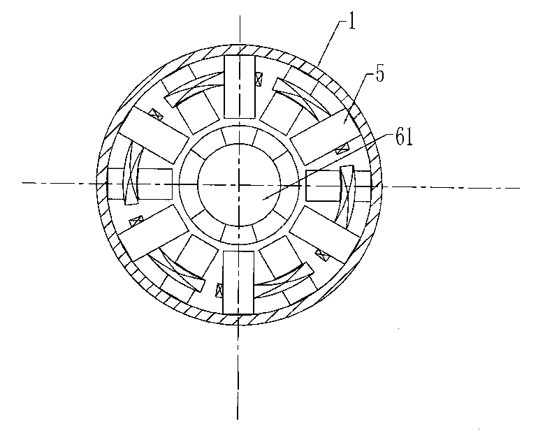
[0007] Specific implementation mode 1. Combination figure 1 and figure 2 ,as well as Figure 21 Describe this embodiment, this embodiment it is made up of casing 1, stator and rotor 6; Rotor is made up of permanent magnet array and rotor yoke 61; Stator is made up of several phase units 2; Phase unit 2 is made up of several phase armature cores 3 and phase armature winding 4; each phase armature core 3 is composed of 2k core units 5, and each phase armature core 3 is composed of 2k core units 5. The phase armature core with tooth holes 71, The tooth hole 71 is formed by stacking the tooth slots 72 of 2k core units 5, and each core unit 5 is composed of two teeth and a yoke segment; the two teeth are arranged in the axial direction, and the two teeth A yoke segment is connected between them; 2k core units 5 are arranged at equal intervals in the casing 1 along the circumferential direction; the coil 41 is wound into a phase armature winding 4 through the tooth holes 71 of t...
specific Embodiment approach 2
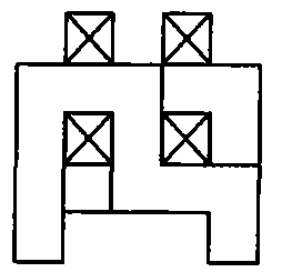
[0008] Specific embodiment two, combine Figure 3 to Figure 6 Describe this embodiment, the difference between this embodiment and the specific embodiment is that each core unit 5 in the phase armature core 3 is composed of a long tooth 51, a short tooth 52, a high-level yoke segment 53, a The low horizontal yoke section 54 and a vertical yoke section 55 are composed; the long teeth 51 and the short teeth 52 are arranged along the horizontal direction of the cross section, and the long teeth 51 and the short teeth 52 are sequentially connected with The high level yoke section 53, the vertical yoke section 55 and the low level yoke section 54, the side root of the long tooth 51 is connected to the side of one end of the high level yoke section 53, and the high level magnetic The other side of the yoke section 53 is connected to the root of one side of the vertical yoke section 55, and the other side of the vertical yoke section 55 is connected to the bottom of the low horizonta...
specific Embodiment approach 3
[0009] Specific embodiment three, combine figure 1 , image 3 and Figure 4 Describe this embodiment. The difference between this embodiment and the specific embodiment is that the coil 41 is circularly wound on the upper part of the long tooth 51 or the high horizontal yoke segment 53 or the vertical yoke segment 55 through the two tooth holes 71 into a phase-phase armature winding 4. Other compositions and connection methods are the same as those in Embodiment 1.
PUM
 Abstract
Description
Claims
Application Information
 - R&D
- Intellectual Property
- Life Sciences
- Materials
- Tech Scout
- Unparalleled Data Quality
- Higher Quality Content
- 60% Fewer Hallucinations
Browse by: Latest US Patents, China's latest patents, Technical Efficacy Thesaurus, Application Domain, Technology Topic, Popular Technical Reports.
© 2025 PatSnap. All rights reserved.Legal|Privacy policy|Modern Slavery Act Transparency Statement|Sitemap|About US| Contact US: help@patsnap.com


