Turn-off device-based mobile power transmission device

A power transmission device, mobile technology, applied in the direction of circuit devices, electrical components, AC network circuits, etc., can solve the problems of large area occupied by the converter station, insufficient guarantee of system stability, commutation failure, etc.

Active Publication Date: 2010-06-16
ZHUZHOU NAT ENG RES CENT OF CONVERTERS
View PDF0 Cites 20 Cited by
  • Summary
  • Abstract
  • Description
  • Claims
  • Application Information

AI Technical Summary

Problems solved by technology

[0004] (1) The traditional AC power transmission technology, which adopts the form of AC overhead wire transmission, requires that all synchronous generators in the AC power system must ensure synchronous operation, and the stability of the system cannot be fully guaranteed; use AC transmission lines to connect When there are two or more AC systems, the short-circuit capacity increases, and even need to replace the circuit breaker or add a current limiting device; when there is no empty space and light load, the receiving end and the middle part of the AC long line are prone to abnormal voltage rise, and parallel reactance compensation is required ; Since the AC is transmitted by three lines, the cost of the line is high, the annual power loss rate is large, and it is easy to generate a large amount of reactive power loss of inductive reactance and capacitive reactance
[0005] (2) Thyristor-based current source converter type DC power transmission technology, this method can only work in the active inverter state, and the receiving end system must have a large enough short-circuit capacity, otherwise commutation failure will easily occur; commutation The harmonic frequency generated by the converter is low and the capacity is large; the converter needs to absorb a large amount of reactive power and requires a large number of filtering and reactive power compensation devices; the converter station occupies a large area and requires a large investment
[0006] The power transmission technology based on turn-off devices is very professional, but the four-quadrant power transmission technology for active power and reactive power has not yet appeared. In the current engineering implementation process, only a single active power transmission technology can be seen. Transmission or separate transmission technology for reactive power compensation, such as the 138kV, ±100Mvar STATCOM device delivered to the Talega power station of SDG&E (San Diego Gas&Electric) in the United States in October 2002

Method used


Image

  • Turn-off device-based mobile power transmission device
  • Turn-off device-based mobile power transmission device
  • Turn-off device-based mobile power transmission device

Examples


Embodiment Construction

[0032] The accompanying drawings show specific embodiments of the present invention, and the present invention will be further described below through the accompanying drawings and the embodiments.

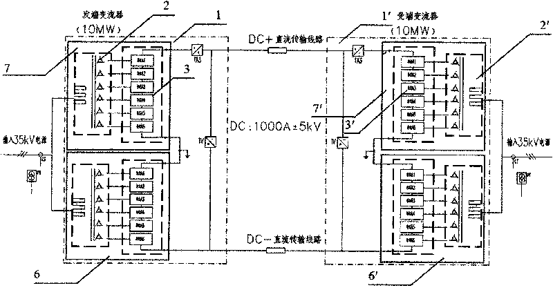
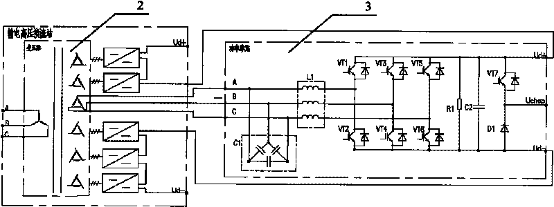
[0033] Such as figure 2 As shown, for the structure of the mobile power transmission device based on turn-off devices, it includes two sets of independent high-voltage converter stations (such as figure 2 1 and 1′), the two groups of converter stations are combined in parallel through the DC side in the back-to-back connection mode, and are respectively used as the sending end (also known as the sending end) and the receiving end (also called the receiving end) of the DC transmission. Each group of high-voltage converter stations includes a pair of modules in series (such as figure 2 6, 7, 6', 7'), each module consists of a phase-shifting transformer (such as figure 2 2 and 2′) and several power units (such as figure 2 3 and 3' part shown in the middle mark) composition. Ea...


PUM


Abstract

The invention relates to a turn-off device-based mobile power transmission device, which comprises two groups of independent high-voltage converter stations. The two groups of independent high-voltage converter stations are combined together through parallel connection on a DC side in a back-to-back connection mode and are taken as a transmitting end and a receiving end for DC power transmission respectively, wherein the transmitting end is connected with a three-phase AC output terminal of an electric network; and the receiving end can be connected with an active electric network or a passive electric network according to the requirements of the power transmission. The power transmission method adopts a two-layer control mode of upper layer control and lower layer unit control, wherein the upper layer control mainly coordinates control targets of power units of a plurality of converters and system protection, and the lower layer unit control performs real-time control and protection on the power units. The mobile power transmission device has the characteristics of small size, high efficiency, flexible control and the like, improves the operating range and the utilization ratio of the device and also greatly improves the quality of electric energy.

Description

technical field [0001] The invention relates to a power transmission device, especially a mobile power transmission device based on a switchable device applied in the field of power transmission and transformation. The power transmission device can also be used for small-scale decentralized renewable energy sources (such as wind power, solar energy, etc.) ) grid-connected power plants, sensitive load power supply, urban load center power supply, offshore drilling platform power supply, and isolated island power supply. Background technique [0002] With the country's vigorous development and utilization of renewable clean energy, the continuous optimization of the energy structure, and the continuous expansion of the use of renewable energy such as wind energy and solar energy, its inherent characteristics of dispersion, small size, and distance from the load center continue to show up. However, the adoption of traditional power transmission technology brings a series of un...

Claims


Application Information

Patent Timeline
IPC IPC(8): H02J3/26H02J3/18H02J3/00
CPCY02E60/60Y02E40/50Y02E40/30
Inventor 王小方周细文敬华兵梁之渊章辉李军张志学邓明梁金成刘彤
Owner ZHUZHOU NAT ENG RES CENT OF CONVERTERS
Why Eureka
Try Eureka