
Battery system

A battery system and battery technology, applied in secondary batteries, battery pack components, battery overcharge protection, etc., can solve problems such as contact welding and inability to cut off current.

Active Publication Date: 2010-06-16
SANYO ELECTRIC CO LTD
View PDF1 Cites 25 Cited by
  • Summary
  • Abstract
  • Description
  • Claims
  • Application Information

AI Technical Summary

Problems solved by technology

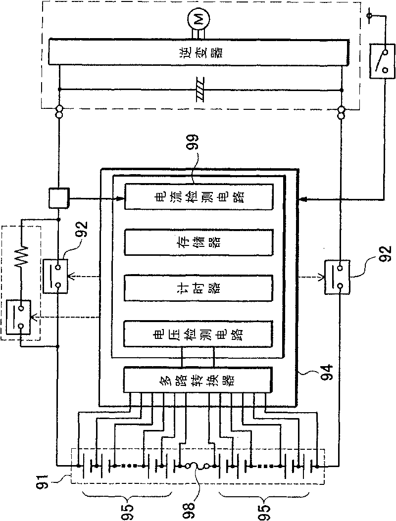
therefore, figure 1 The disadvantage of the battery system shown is that when the control circuit 94 detects the overcurrent of the battery 91 and controls the relay 92 to be disconnected, if the overcurrent is larger than the maximum cutoff current, the contacts of the relay 92 are welded and the current cannot be cut off.

Method used


Image

  • Battery system
  • Battery system
  • Battery system

Examples


Embodiment Construction

[0021] Hereinafter, embodiments of the present invention will be described based on the drawings. Among them, the embodiments shown below illustrate the battery system for embodying the technical idea of ​​the present invention, but the present invention does not specify the battery system as described below.

[0022] In addition, in this specification, in order to facilitate understanding of the claims, numbers corresponding to the members shown in the embodiments are added to the members shown in the "claims" and "means to solve the problem" column. However, the components shown in the claims are not limited to the components of the embodiment.

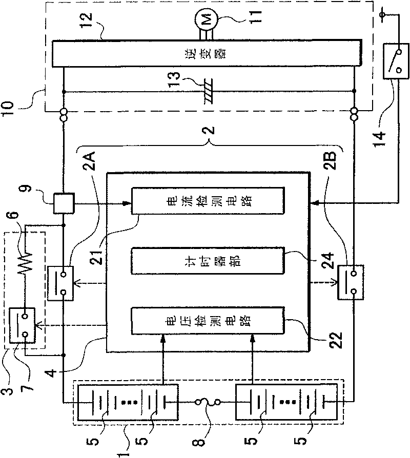
[0023] figure 2 The illustrated battery system is mounted on a vehicle such as a hybrid car, a fuel cell vehicle, or an electric vehicle, and drives an electric motor 11 connected as a load to drive the vehicle. A motor 11 serving as a load 10 of the battery 1 is connected to the battery 1 via an inverter 12 . The inverter 12 co...


PUM


Abstract

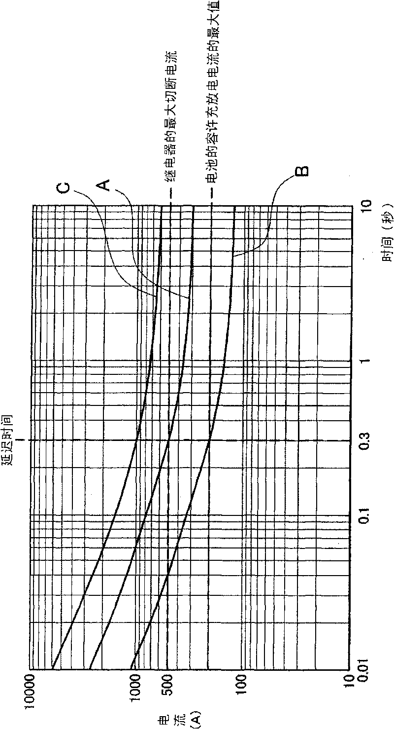
The battery system is provided with a battery (1) that can be recharged, a fuse (8) connected to the battery (1) that blows with excessive current flow, relays (2) connected to the output-side of the battery (1), and a current cut-off circuit (4) that detects excessive battery (1) current and controls the relays (2). The current cut-off circuit (4) detects excessive battery (1) current, and is provided with a timer section (24) that designates a time delay until the relays (2) are switched from ON to OFF. For the delay time of the timer section (24), the fusing current of the fuse (8) is set lower than the maximum cut-off current of the relays (2) and higher than the maximum allowable battery (1) charging and discharging current. In a situation where excessive current greater than the maximum cut-off current of the relays (2) flows through the battery (1), the fuse (8) is blown during the timer (24) delay time, and the current cut-off circuit (4) switches the relays (2) from ON to OFF when the delay time has elapsed.

Description

technical field [0001] The present invention relates to a battery system suitable for a power supply device for a vehicle that supplies electric power to a motor that drives the vehicle, and more particularly to a battery system that detects overcurrent and cuts off the current of the battery using a fuse and a relay. Background technique [0002] In order to prevent battery overcurrent, a battery system is being developed in which a fuse and a relay are connected in series (see Patent Document 1). [0003] The battery system of Patent Document 1 such as figure 1 As shown, the battery 91 is divided into two battery packs 95, and the battery packs 95 are connected in series via a fuse 98. Furthermore, a relay 92 is connected to an output terminal of the battery 91 . In this battery system, the fuse 98 is blown to cut off the current of the battery 91 when a current flows through the running battery. In addition, in this battery system, the control circuit 94 that controls ...

Claims


Application Information

Patent Timeline
Patent Type & Authority Applications(China)
IPC IPC(8): H01M10/48H01M2/34H01M10/42H01M10/00H01M50/583H01M50/588H01M50/59
CPCY02T10/7055B60L11/1864Y02T10/7044Y02T10/7061B60L11/1803Y02T10/7011B60L3/04B60L3/0046B60L3/0069B60L11/1862B60L2240/547Y02T10/7005B60L2270/20H02J7/0026B60L3/0053B60L2240/80B60L2240/549Y02T90/34H02H9/001B60L50/51B60L58/21B60L58/15B60L58/18H02J7/0014Y02T10/70H02J7/00302H02J7/00304H02H7/18H01H85/46Y02T90/40
Inventor 古川公彦矢野准也田中邦穗
Owner SANYO ELECTRIC CO LTD
Learn More