Method for demarcating four-quadrant detector in real time

A four-quadrant, detector technology, applied in the direction of instruments, measuring devices, optical devices, etc., can solve the problems of measurement error, time-consuming, inconvenient operation, etc., and achieve the effect of simple and fast operation, wide application range, and real-time accurate acquisition

Inactive Publication Date: 2010-06-16
INST OF PHYSICS - CHINESE ACAD OF SCI
View PDF0 Cites 8 Cited by
  • Summary
  • Abstract
  • Description
  • Claims
  • Application Information

AI Technical Summary

Problems solved by technology

[0008] The purpose of the present invention is to overcome the shortcomings of the traditional calibration method for four-quadrant photodiode detectors, which are inconvenient to operate, take a long time, and easily cause measurement errors, thereby providing a four-quadrant photodiode detector with simple operation and high measurement accuracy

Method used


Image

  • Method for demarcating four-quadrant detector in real time
  • Method for demarcating four-quadrant detector in real time
  • Method for demarcating four-quadrant detector in real time

Examples


Embodiment Construction

[0039] The present invention will be described below in conjunction with the accompanying drawings and specific embodiments.

[0040] In one embodiment of the present invention, a common optical tweezers system is taken as an example to illustrate how to use the method of the present invention in this system.

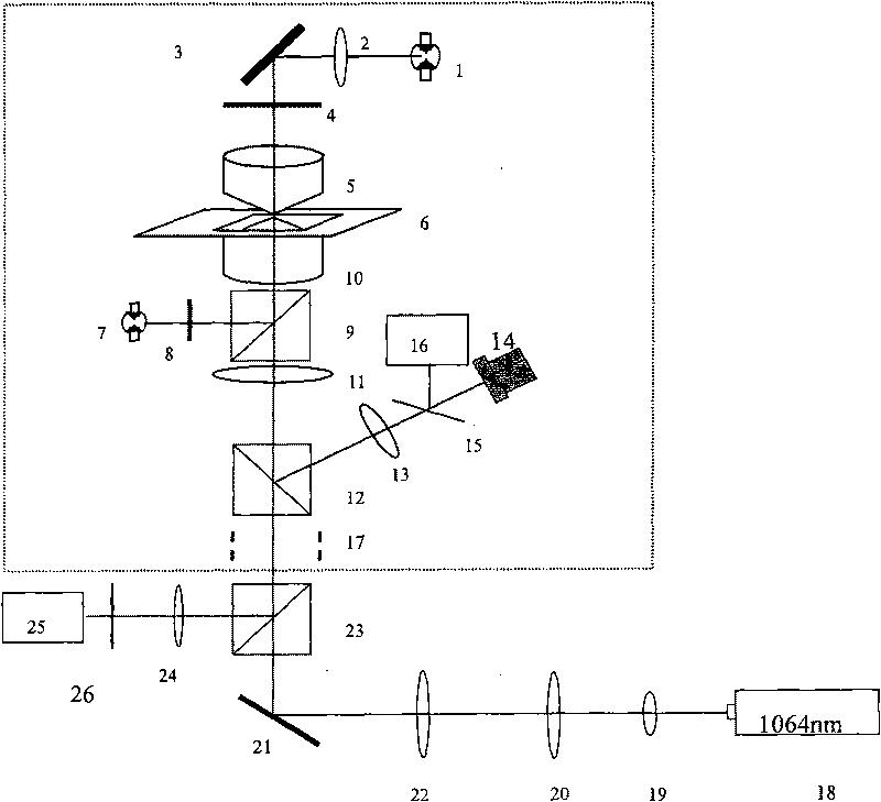
[0041] exist image 3In , a schematic diagram of an optical tweezers system is given. It can be seen from the figure that the optical tweezers system includes an inverted research optical microscope, a charge-coupled device (CCD, ChargeCoupled Device) and a four-quadrant photodiode detector (QD), in addition, also includes other necessary optical components, such as lenses, mirrors, etc. Wherein, the inverted research optical microscope is represented by the dotted line frame in the figure, and it includes a halogen lamp (Halogen Lamp) 1, a first lens 2, a first reflector 3, a first filter 4, and a condenser 5. Koehler illumination system to form uniform bright field ...


PUM


Abstract

The invention provides an optical measuring system. The system comprises a four-quadrant photodiode detector, a detected-object image generating device and a stepping motor which is provided with a glass slide and can drive the glass slide to vibrate, wherein the stepping motor is arranged between the four-quadrant photodiode detector and the detected-object image generating device and enables light rays radiated from the detected-object image generating device to the four-quadrant photodiode detector to straightly penetrate through the glass slide on the stepping motor. Based on the relationship between the distance of the light rays shifted by the glass slide and the output signals of the four-quadrant photodiode detector, the invention directly demarcates the switching coefficient between the output voltage of the four-quadrant photodiode and the displacement of the image of the detected object without making any regulation to the original light path system, thereby achieving the advantages of simple and convenient operation and real-time and accurate acquisition of experimental parameters.

Description

technical field [0001] The invention relates to a calibration method for optical equipment, in particular to a method for real-time calibration of a four-quadrant detector Background technique [0002] Four-quadrant photodiode detector (QD) is a photodetector device that arranges four photodiodes with exactly the same performance according to the requirements of rectangular coordinates. It is often used in laser guidance or laser alignment. It has the characteristics of high sensitivity, fast response (up to sub-millisecond level), high measurement accuracy, digital storage of collected signals, and easy subsequent processing, so it has been valued and applied in the field of displacement measurement. The basic structure of a four-quadrant photodiode detector is as follows: figure 1 As shown, it consists of four photodiodes with the same parameters, which are located in four quadrants of a circular surface. When light shines on the detector, due to the photovoltaic effect,...

Claims


Application Information

Patent Timeline
IPC IPC(8): G01B11/02
Inventor 郭红莲屈娥凌林黄璐李兆霖张道中李志远
Owner INST OF PHYSICS - CHINESE ACAD OF SCI
Why Eureka
Try Eureka