
Space environmental temperature and humidity control method and control device thereby

A technology of temperature and humidity control and space environment, applied in non-electric variable control, space heating and ventilation, control/regulation systems, etc., can solve problems such as large energy consumption, affecting temperature, and energy waste

Inactive Publication Date: 2010-06-16
黄逸林
View PDF0 Cites 69 Cited by
  • Summary
  • Abstract
  • Description
  • Claims
  • Application Information

AI Technical Summary

Problems solved by technology

Temperature fluctuations will cause relative humidity to deviate from the control target value, and the adjustment of humidity will also affect the balance of temperature, so that the two control loops are always in a state of constant adjustment to meet the control requirements, resulting in actuators such as chilled water control valves and steam The control valve frequently works hard and is often in a state of antagonistic and counteracting effects, especially when high temperature and humidity target accuracy is required under high temperature and high humidity climate conditions, the energy consumption is very large, and the system work is very unstable
In the unstable state of the system, in order to ensure the reliable drying of the target space, a large margin must be reserved for the control value during humidity control, which further leads to waste of energy

Method used


Image

  • Space environmental temperature and humidity control method and control device thereby
  • Space environmental temperature and humidity control method and control device thereby
  • Space environmental temperature and humidity control method and control device thereby

Examples


Embodiment 1

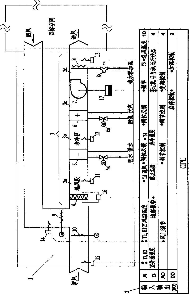
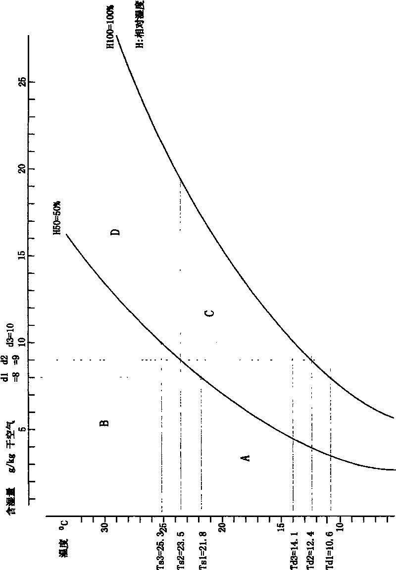
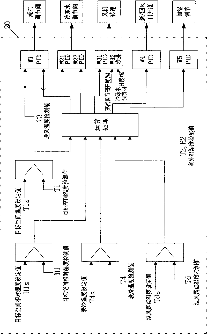
[0051] Figure 4 A first embodiment of the control flow is shown. This example uses as figure 1 The air-conditioning unit and controller shown in the figure, the control target to be achieved is that the upper limit of the relative humidity of the air in the target space is a certain value, that is, the relative humidity figure 2 The enthalpy-humidity schematic diagram shows that the dew point temperature Td2 corresponding to the intersection point of the relative humidity curve with a relative humidity of 50% and the 23.5°C isotherm is 12.4°C, so the upper limit of the dew point temperature, that is, the dew point temperature setting value Tds is predetermined to be 12.4°C At the same time, the temperature of 12.4°C is also used as the temperature setting value T4s after cooling of the surface for monitoring the temperature of the cooling surface, and they are stored in the storage unit of the controller. unit.

[0052] The control flow of the first embodiment is as follow...

Embodiment 2

[0061] Figure 5 The control flow of Embodiment 2 of the present invention is shown, and the upper limit of the relative humidity of the control is a certain interval.

[0062] This control procedure can be applied, for example, to air-conditioning units in the candy production area of ​​a large candy factory. This area is required to ensure a certain degree of dryness, that is, the upper limit of relative humidity has certain requirements but is not strict. It can be an interval, and the lower limit of relative humidity is not strictly required. Generally speaking, the drier the better. According to the requirements of the production process, the upper limit of the relative humidity control target is 45% to 55%; the temperature control target is 23.0 to 25.0°C. Based on the temperature and humidity target value, the dew point temperature Tds for determination in the main process is determined to be 12.4° C., which is the same as that in Example 1. The set value of the dew p...

Embodiment 3

[0074] Some factories or laboratory spaces have strict relative humidity and temperature control requirements, and the relative humidity control target is a certain value. In this case, the relative humidity control target = 50%; the temperature control target = 23.5°C. When the relative humidity of the target space is lower than 50%, humidification control is required; when the relative humidity of the target space is higher than 50%, dehumidification control is required. The temperature control target is also a definite value.

[0075] For the main control process of this embodiment, please refer to the attached Figure 6 : "relative humidity is a control process of a certain value." Its basic control method is: monitor the dew point temperature of the mixed air in the new return air mixing section, and judge which control requirement it meets. Different control strategies are determined according to the mixed air dew point temperature value. If the mixed air dew point tem...


PUM


Abstract

The invention discloses a space environmental temperature and humidity control method and a control device thereby. In the method, a controller controls the operation of an actuating mechanism used for adjusting temperature and humidity according to temperature and humidity monitoring results so as to control the temperature and humidity of air; according to the required temperature and relative humidity of a target space, a set air dew-point temperature value of a mixed air section is set in advance in a storage; the controller compares a monitored air dew-point temperature monitored value of the mixed air section, which is monitored by a dew-point temperature sensor, with the set air dew-point temperature value of the mixed air section, which is set in advance, and judges whether the actuating mechanism is used to cool the air to lower the humidity or not; and after the adjustment decision is made, a temperature control procedure starts. Since the monitoring adjustment decision making step of the air dew-point temperature value of the mixed air section is repeated according to a set cycle in the running process of an air conditioning unit, the method can carry out necessary control of lowering humidity, raising or reducing temperature as required. The invention not only can greatly save energy, but also can stabilize a control system and realize high-accuracy control by using the control system, the temperature control and the humidity control of which are not interfered.

Description

technical field [0001] The invention relates to a space environment temperature and humidity control method using an air conditioning unit to control the temperature and humidity of air in a target space and a space environment temperature and humidity control device used in the method. Background technique [0002] At present, for space areas that require temperature and humidity control, such as candy production and packaging workshops, spinning workshops, and satellite assembly sites, air-conditioning units with dehumidification functions are generally used to control the temperature and humidity of the target space. This air-conditioning unit is equipped with a sensor for monitoring the air temperature and relative humidity in the target space, a surface cooler for cooling or even cooling and dehumidifying the air flowing through the air-conditioning unit, and a heater for heating the air, as well as the air temperature and relative humidity in the target space. Controll...

Claims


Application Information

Patent Timeline
IPC IPC(8): F24F11/00F24F11/053G05D27/02F24F11/76
Inventor 黄逸林
Owner 黄逸林
Learn More