
Screen dot design method of side light type light guide plate of LED light source

A technology of dots on light guide plates and LED light sources, which can be applied in the direction of light guides, light sources, point light sources, etc., and can solve the problem that the dot design of LED side-light backlight modules is difficult to complete in one step

Inactive Publication Date: 2010-06-16
GUANGZHOU UNIVERSITY
View PDF0 Cites 18 Cited by
  • Summary
  • Abstract
  • Description
  • Claims
  • Application Information

AI Technical Summary

Problems solved by technology

[0006] The purpose of the present invention is to overcome the deficiencies of the prior art, aiming at the defect that the network point design of the current LED side-light type backlight module is difficult to complete in one step, a method for designing the network point of the side-light type light guide plate of the LED light source is proposed

Method used


Image

  • Screen dot design method of side light type light guide plate of LED light source
  • Screen dot design method of side light type light guide plate of LED light source
  • Screen dot design method of side light type light guide plate of LED light source

Examples


Embodiment 1

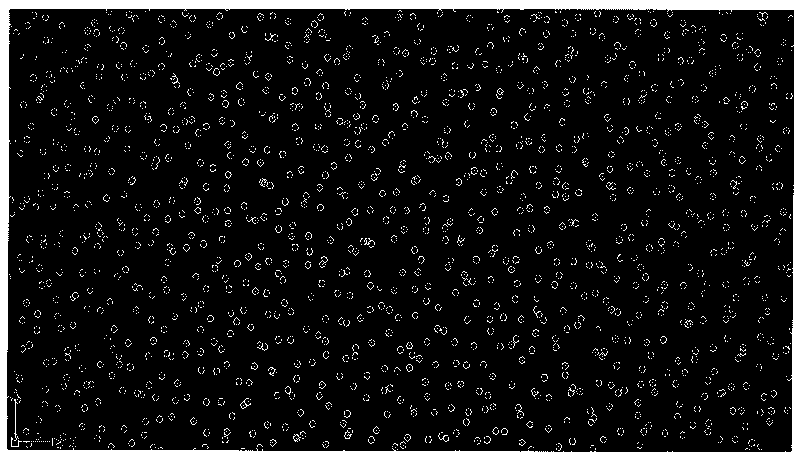
[0051] In order to verify the effect of the application of the present invention on the light guide plate, we will use the user interface of the present invention to generate dots, the length of the light-emitting area is 69.7mm, the width of the light-emitting area is 32.48mm, the relative density value is 0.75, and the number of LEDs is 5. The corresponding LED coordinates are (3.248, 0), (9.744, 0), (16.24, 0), (22.736, 0), (29.232, 0). Enter these parameters Image 6 Click the "OK to generate network" button in the user interface to get the following Figure 7 network points shown. We input the obtained dots into the laser engraving machine and engrave them on the mold core, and then transfer the dots to the light guide plate through plastic molding. It can be seen from the test results that the optical effect of the backlight module can be effectively controlled by using the dots of the light guide plate generated by the present invention, and the uniformity of the back...

Embodiment 2

[0053] Figure 8 It is the dot pattern of the light guide plate of a single LED, the relative density of dots is 0.9, the length of the light-emitting area is 20mm, and the width of the light-emitting area is 20mm. The LED is located in the lower right corner of the entire light-emitting area, from Figure 8 It can be seen that the dot density increases with the increase of the distance between the dot position and the LED.

Embodiment 3

[0055] Figure 9 It is the dot pattern of the light guide plate of two LEDs, the relative density of the dots is 0.9, the length of the light-emitting area is 20mm, and the width of the light-emitting area is 20mm. The coordinate positions of the LEDs are: (5, 0); (15, 0).


PUM


Abstract

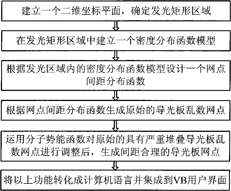
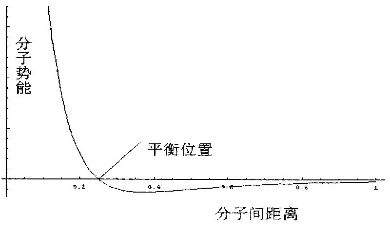
The invention provides a screen dot design method of a side light type light guide plate of an LED light source, comprising the following steps of: establishing a two-dimensional coordinate plane, and determining a rectangular lighting area; establishing a density distribution function model in the rectangular lighting area; designing a screen dot space distribution function according to the density distribution function model inside the rectangular lighting area; generating original light guide plate random number screen dots according to the screen dot space distribution function; providing an intermolecular potential energy function, regulating the original light guide plate random number screen dots with serious stacking by applying the intermolecular potential energy function, and then generating light guide plate screen dots with reasonable spaces; converting the density distribution function model, the screen dot space distribution function and an intermolecular potential energy function model into computer languages by a VBA development tool facing to objectification, and establishing a VB user interface (VB form). The invention enhances the development speed of the light guide plate and overcomes the defect of manual regulation needed in the screen dot design process of the light guide plate.

Description

technical field [0001] The invention belongs to the technical field of side-light light guide plate outlets of LED light sources, and in particular relates to a design method for side-light light guide plate outlets of LED light sources. technical background [0002] At present, LED (Light Emitting Diode) is more and more used as the light source of backlight module. LED is a point light source, while the traditional CCFL (cold cathode tube) is a line light source. of. As an indispensable backlight module in liquid crystal display devices, it is in a stage of rapid development along with the popularization of liquid crystal display devices. The light guide plate is a key component of the backlight module, and it is of great significance to improve the overall optical effect of the backlight module. The development of high-efficiency light guide plates has become a hot topic in the backlight industry. [0003] Traditional backlight modules, especially large-size backlight ...

Claims


Application Information

Patent Timeline
IPC IPC(8): F21V8/00G02F1/13357F21Y101/02
Inventor 康敏武郭康贤
Owner GUANGZHOU UNIVERSITY
Learn More