
Process of manual submerged-arc welding in welding position of doorframe and tower section

A welding position, submerged arc welding technology, applied in welding/welding/cutting items, welding equipment, arc welding equipment, etc., can solve the problems of high skill requirements for welding workers, poor welding environment for welding workers, and easy generation of welding stress, etc. Achieve the effect of reducing the skill level of workers, shortening the production cycle, and high welding pass rate

Inactive Publication Date: 2010-06-16
TITAN (SUZHOU) METAL PROD CO LTD
View PDF0 Cites 5 Cited by
  • Summary
  • Abstract
  • Description
  • Claims
  • Application Information

AI Technical Summary

Problems solved by technology

The conventional welding method has a poor welding environment for welders, and the welding time is long, which requires high skills for the welders, and the special conventional welding method for the position of the door frame has a small amount of single-pass deposition and a large number of welding passes, which is easy to increase the risk of welding defects produced; therefore, at this position, conventional welding methods are used to weld and produce high cost and low production efficiency
Moreover, the surroundings of the door frame of the wind tower after assembly and spot welding are almost completely constrained, and the difference in heat dissipation capacity between the door frame and the tower body is extremely easy to generate welding stress, while the conventional welding method has a small single-pass weld deposition cross-section, which is easy to be damaged. Welding stress cracks; once a welding crack defect occurs, it will take a lot of auxiliary time for repair, even reaching more than 3 times the repair time consumption of welding a door frame

Method used


Image

  • Process of manual submerged-arc welding in welding position of doorframe and tower section
  • Process of manual submerged-arc welding in welding position of doorframe and tower section
  • Process of manual submerged-arc welding in welding position of doorframe and tower section

Examples


Embodiment 1

[0020] The manual submerged arc welding process of the welding position between the door frame of the wind tower and the corner welding of the tower body and the tower joint, the specific operation steps are as follows:

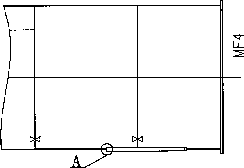
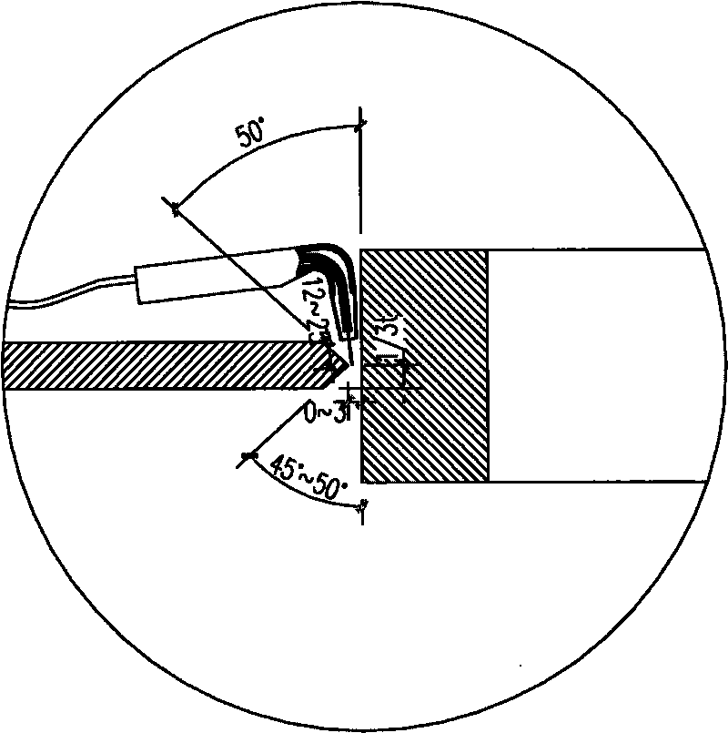
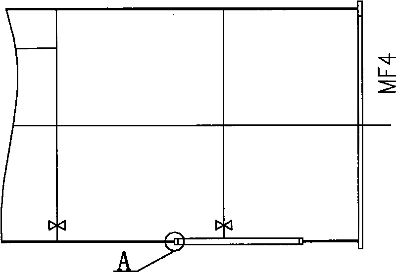
[0021] (a) Bending 60MM steel plates and splicing them into a wind tower door frame, and inserting the wind tower door frame into the tower tube; that is, inserting the tower body into the bottom section of the tower tube in the form of a T-joint (such as figure 1 , figure 2 shown);

[0022] (b) Remove pollutants on the surface of the wind tower weld and the surrounding gas-cut oxidation surface;

[0023] (c) Preheating before welding, heating the surroundings of the weld to 70°C;

[0024] (d) CO2 welding is used for the inner side of the wind tower door frame and tower body angle; the CO2 purity is 99%; the welding wire is TM-58;

[0025] (e) Submerged arc automatic welding is adopted between the door frame of the wind tower and the outer corner of the t...

Embodiment 2

[0031] Other is identical with embodiment 1, and welding process parameter is as follows:

[0032]

Embodiment 3

[0034] Other is identical with embodiment 1, and welding process parameter is as follows:

[0035]


PUM


Abstract

The invention discloses a process of manual submerged-arc welding in the welding position of a doorframe and a tower section. The process comprises the following specific operation steps of: embedding a doorframe of a wind tower in a tower cylinder; removing contaminants on the weld surface of the wind tower and a surrounding gas-cut oxidized surface; welding the front doorframe of the wind tower and the outer side of the tower body corner by adopting the automatic submerged-arc welding; and welding the doorframe of the wind tower and the inner side of the tower body corner by adopting the automatic submerged-arc welding again. By adopting a more reasonable welding sequence, the process of the manual submerged-arc welding in the welding position of a doorframe and a tower section does not need the backstep welding or the backstep welding in a small area, thereby achieving the higher qualification rate of the welding; and simultaneously, the invention improves the work environment of welders, enhances the production and work efficiency, shortens the production cycle and lowers the manufacturing cost.

Description

technical field [0001] The invention relates to a welding process, in particular to a manual submerged arc welding process for welding the fillet welds between a wind tower door frame and a tower body. Background technique [0002] In the manufacturing process of the wind tower, due to the particularity of the welding position, the traditional automatic submerged arc welding method cannot be used for the corner welding of the wind tower door frame and the tower body plate. Only conventional welding methods can be used: manual arc welding or carbon dioxide gas Shielded welding. The conventional welding method has a poor welding environment for welders, and the welding time is long, which requires high skills for the welders, and the special conventional welding method for the position of the door frame has a small amount of single-pass deposition and a large number of welding passes, which is easy to increase the risk of welding defects Produced; therefore, at this position,...

Claims


Application Information

Patent Timeline
Patent Type & Authority Applications(China)
IPC IPC(8): B23K9/18B23K9/235B23K101/24
Inventor 朱国学陈巍
Owner TITAN (SUZHOU) METAL PROD CO LTD
Learn More