Electrostatic atomizer

An electrostatic sprayer, high-voltage electrostatic generation technology, applied in the direction of electrostatic spraying device, spraying device, spraying electric energy device, etc., can solve the problems of poor reliability of electrostatic generator, abnormal operation of oscillator, not easy to be small and compact, etc., and achieve small appearance and volume Effect

Inactive Publication Date: 2010-06-16
苏州稼乐植保机械科技有限公司
View PDF0 Cites 4 Cited by
  • Summary
  • Abstract
  • Description
  • Claims
  • Application Information

AI Technical Summary

Problems solved by technology

[0005] However, the circuit characteristics of general electrostatic sprayers and their defects, such as attached figure 2 In the common circuit diagram of the general electrostatic generating device shown, the multivibrator is composed of transistor T, transformer B and capacitor C. The feedback of L2 through C is the condition for maintaining oscillation, and the frequency of oscillation is determined by L1 and distributed capacitance C1.
[0006] This circuit is simple and has been widely used in some industries, but the circuit has high requirements on the characteristics of the transistor T and the value of L2 in the transformer B. At the same time, it will cause resonance frequency and feedback after external processing such as packaging. The change of intensity will make the oscillator work abnormally, even stop the vibration and cannot run, resulting in no high-voltage static electricity, and the reliability of the static electricity generator is poor
[0007] Moreover, the voltage doubling circuit composed of high-voltage capacitors and high-voltage diodes is not easy to be small and compact under high-voltage conditions, and cannot be used in occasions where the size of the electrostatic generator is required to be small

Method used


Image

  • Electrostatic atomizer
  • Electrostatic atomizer
  • Electrostatic atomizer

Examples


Embodiment Construction

[0030] The preferred embodiment of the present invention will be described in detail below in conjunction with accompanying drawing:

[0031] as attached image 3 An electrostatic sprayer shown includes a liquid storage container 1 , a high-voltage electrostatic generating device 2 with positive and negative electrodes, a connecting hose 5 , and a spray gun 3 . One end of the connecting hose 5 communicates with the liquid storage container 1 , and the other end of the connecting hose 5 communicates with the rear end of the spray gun 3 .

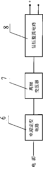
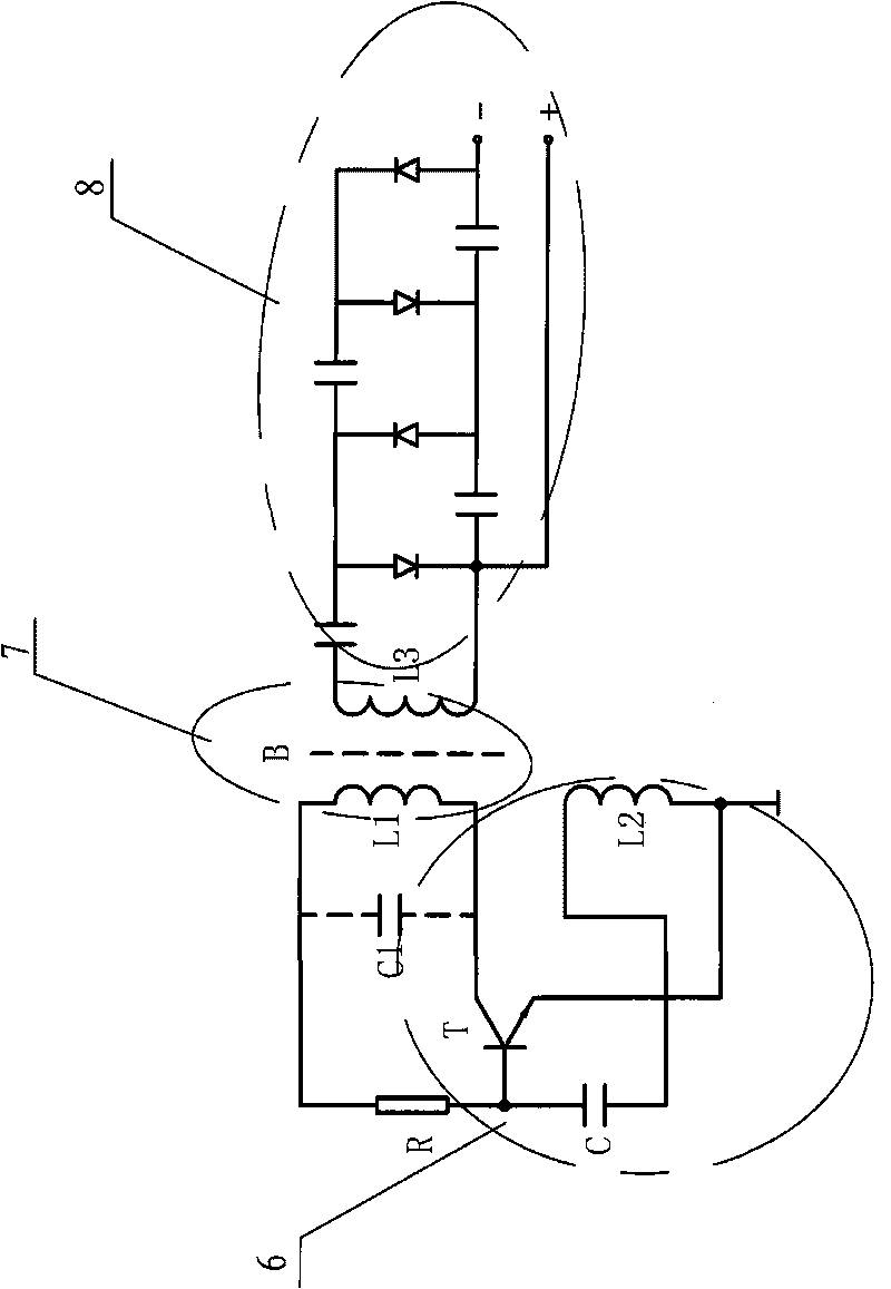
[0032] as attached Figure 4 Shown, described high-voltage electrostatic generator 2 comprises:

[0033] A power inverter circuit 6, the power inverter circuit 6 is used to transform a low-voltage DC power supply into a high-frequency AC power supply;

[0034] High-frequency transformer 7, its input end is electrically connected with the output end of described power inverter circuit 6, and described high-frequency transformer 7 is used fo...


PUM


Abstract

The invention relates to an electrostatic atomizer. The electrostatic atomizer comprises a liquid storage container, a high-voltage electrostatic generator with an anode and a cathode, a connecting hosepipe and a spray gun; the high-voltage electrostatic generator comprises a power inverter circuit, a high frequency transformer and a voltage doubling rectifying circuit; the power inverter circuit comprises a multivibrator which is formed by an integrated circuit; and the multivibrator comprises a 555 integrated time-base circuit, external resistances R1 and R2, and external capacitances C1 and C2. The frequency of the multivibrator consisting of the 555 integrated time-base circuit is determined by R1, R2 and C1, and does not change with the rising and the dropping of an applied power and the change of other factors, so that when the external environment changes, the multivibrator still can always provide a reliable and stable oscillator signal, and the oscillation stop phenomenon cannot occur; and the special epoxy pouring encapsulation technology is used so that the volume of the high-voltage electrostatic generator can be smaller to meet the use requirements of a plurality of special occasions.

Description

technical field [0001] The invention relates to an electrostatic sprayer, in particular to a high-voltage electrostatic generating device in the electrostatic sprayer. Background technique [0002] In the prior art, a high-voltage static electricity generating device generally consists of three parts: a power inverter circuit, a high-frequency transformer and a voltage doubler rectifier circuit. Due to the needs of the workplace, the electrostatic sprayer has a low working voltage, generally 3.7-24 volts, and is powered by various types of batteries. [0003] The power inverter circuit converts low-voltage DC power into high-frequency AC power, and its frequency can be controlled by components in the circuit. The proper frequency will be adapted to the transistor (or other semiconductor device) and high frequency transformer used. [0004] The high-frequency transformer boosts the high-frequency low voltage obtained by the inverter circuit into a high-frequency high voltag...

Claims


Application Information

Patent Timeline
IPC IPC(8): B05B5/00B05B5/053
Inventor 王维克邱桂生
Owner 苏州稼乐植保机械科技有限公司
Why Eureka
Try Eureka