Annular airbag display for dust collector

A ring-shaped airbag and display technology, applied in the direction of the suction filter, etc., can solve the problems of difficult control of the dimensional accuracy of the coil spring, high failure rate of the indicator movement, immobile or early movement of the indicator, etc., and achieve easy control of the restoring force and inflation pressure. Ease of control and reduced failure rate

Inactive Publication Date: 2010-06-16
LG ELECTRONICS (TIANJIN) APPLIANCES CO LTD
View PDF0 Cites 0 Cited by
  • Summary
  • Abstract
  • Description
  • Claims
  • Application Information

AI Technical Summary

Problems solved by technology

[0016] 1. The dimensional accuracy of the coil spring is difficult to control, which may easily cause the indicator body to move or move prematurely, and the accuracy of the action is poor
[0017] 2. The friction between the spring or the indicator body and the shell is easy to cause the indicator body to not move or move early, so the failure rate of the indicator body action is high, which affects the work of the display

Method used


Image

  • Annular airbag display for dust collector
  • Annular airbag display for dust collector
  • Annular airbag display for dust collector

Examples


Embodiment Construction

[0042] The present invention will be described in detail below with reference to the drawings and examples. In the drawings of the present invention, the same components as those in the prior art have adopted the same symbols.

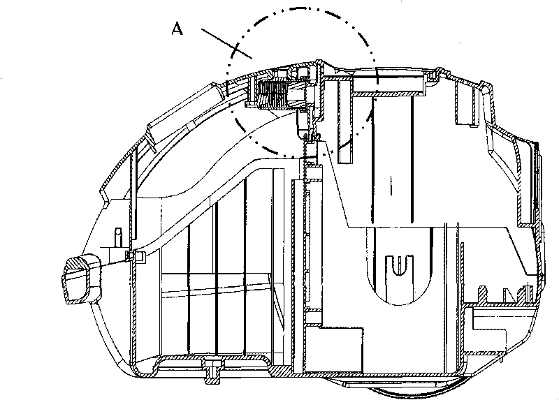
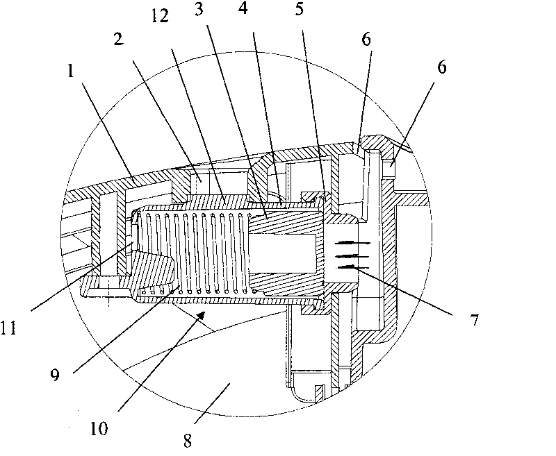
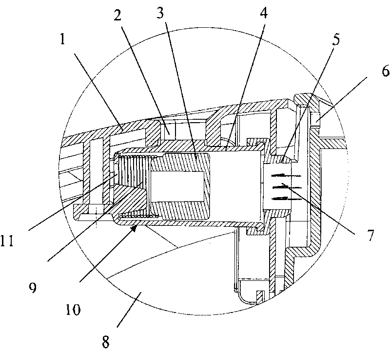
[0043] The annular air bag display of vacuum cleaner of the present invention, as Figure 4 , Figure 5 , Image 6 as shown, Figure 4 It is an assembly drawing of the annular airbag display of the present invention installed on the front cover of the vacuum cleaner; Figure 5 It is the enlarged picture of Part B; Image 6 It is a sectional view of the annular airbag display structure of the present invention.

[0044] Depend on Figure 4 It can be seen that the annular airbag display of the present invention is installed under the display window 2 of the front cover 1 of the vacuum cleaner. Figure 5 The enlarged picture of part B is the original state picture of the annular airbag display when the dust is not full.

[0045] Such as Figure 4...


PUM


Abstract

The invention provides an annular airbag display for a dust collector. The display comprises a shell, a movable indicating body arranged in the shell and a cover connected to the shell, wherein the shell is a round shell of which one end is open while the other end is closed; the center of the closed end is provided with a round convex column projecting inwards; the upper part of the shell is provided with a boss inserted into a display window; the lower part of the shell close to the closed end is provided with an air outlet; the four sides of the indicating body are depressed inwards to form a concave part of which the middle is provided with projecting positioning column; an annular airbag arranged on the round convex column of the shell is also provided; the other end of the annular airbag is inserted into the positioning column of the indicating body; and the middle of the cover is provided with an air inlet, which closes the shell by a disk part and is connected to the shell. The annular airbag is used as a resetting element of the indicating body, and gas with set pressure is filled in the airbag in advance, so the annular airbag display is opened under specific pressure. The size accuracy of the airbag is easy to be ensured and the processing technique is simple, so the indicating body acts correctly and the acting failure rate of the indicating body is lowered.

Description

technical field [0001] The invention belongs to the field of vacuum cleaners, and in particular relates to an annular airbag display for a vacuum cleaner which adopts an annular airbag as a return element of an indicator body. The restoring force of the annular airbag is easy to control, the action of the indicator body is accurate, and the malfunction rate of the indicator body is reduced. Background technique [0002] Vacuum cleaner is a kind of household appliance for indoor cleaning and sanitation, which is used to remove dust from floors, carpets, walls, furniture, clothing and various gaps. Generally speaking, a vacuum cleaner mainly includes a suction device and a suction pipeline. The suction device mainly formed by a motor and a fan is arranged in the body. The suction pipeline includes a suction head and a suction pipe. The air port communicates with the air inlet of the fan inside the body through the telescopic pipe and flexible pipe of the suction pipe. [0003...

Claims


Application Information

Patent Timeline
IPC IPC(8): A47L9/19
Inventor 吕新张国勇
Owner LG ELECTRONICS (TIANJIN) APPLIANCES CO LTD
Why Eureka
Try Eureka