Method and receiver for realizing phase synchronization of coherent light
A phase synchronization and coherent light technology, applied in the field of optical communication, can solve problems such as phase ambiguity and affect the demodulation efficiency of the receiving system, and achieve the effect of improving accuracy and avoiding phase ambiguity
- Summary
- Abstract
- Description
- Claims
- Application Information
AI Technical Summary
Problems solved by technology
Method used
Image
Examples
Embodiment 1
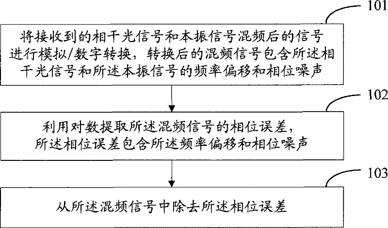
[0029] Embodiment one, see figure 1 Detailed description, figure 1 It is a schematic flow chart of the method in this embodiment.
[0030] Step 101: Perform analog / digital conversion on the mixed signal of the received coherent optical signal and the local oscillator signal, and the converted mixed frequency signal includes the frequency offset and phase noise of the coherent optical signal and the local oscillator signal .
[0031] After the coherent optical signal emitted by the transmitter is transmitted to the receiver through the optical fiber, it is usually sent to the 90-degree optical mixer first, and the local oscillator signal is usually input to the other port of the 90-degree optical mixer, and the other two mixers A port can be set to 0, i.e. ground it. After frequency mixing, the received coherent optical signal and local oscillator signal are usually respectively input into the balanced receiver, and then the output signals of the balanced receiver are passed...
Embodiment 2
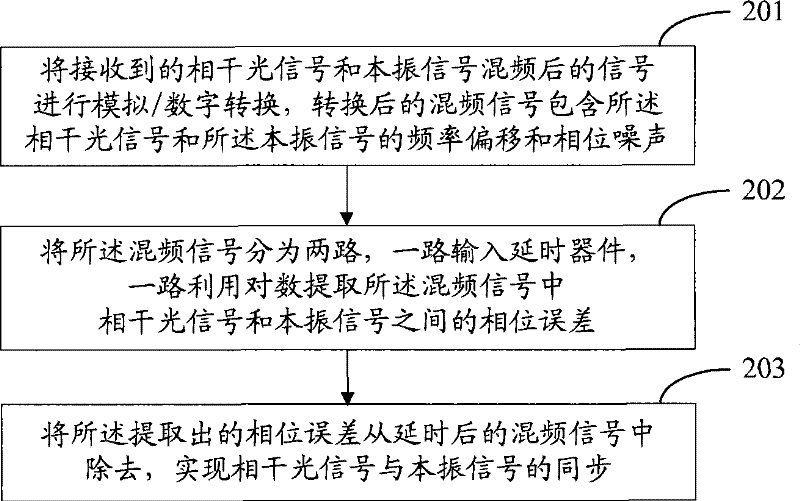
[0043] Embodiment two, see figure 2 Detailed description, figure 2 It is a schematic flow chart of the method in this embodiment.
[0044] Step 201: Perform analog / digital conversion on the mixed signal of the received coherent optical signal and the local oscillator signal, and the converted mixed signal contains the frequency offset and phase noise of the coherent optical signal and the local oscillator signal .
[0045] After frequency mixing, the received coherent optical signal and local oscillator signal are usually respectively input into the balanced receiver, and then the output signals of the balanced receiver are passed through the filter respectively, and the analog / digital conversion is performed, and the converted mixed frequency signal contains all frequency offset and phase noise of the coherent optical signal and the local oscillator signal.
[0046] Step 202: Divide the mixed frequency signal into two paths, one path is input to a delay device, and the o...
Embodiment 3
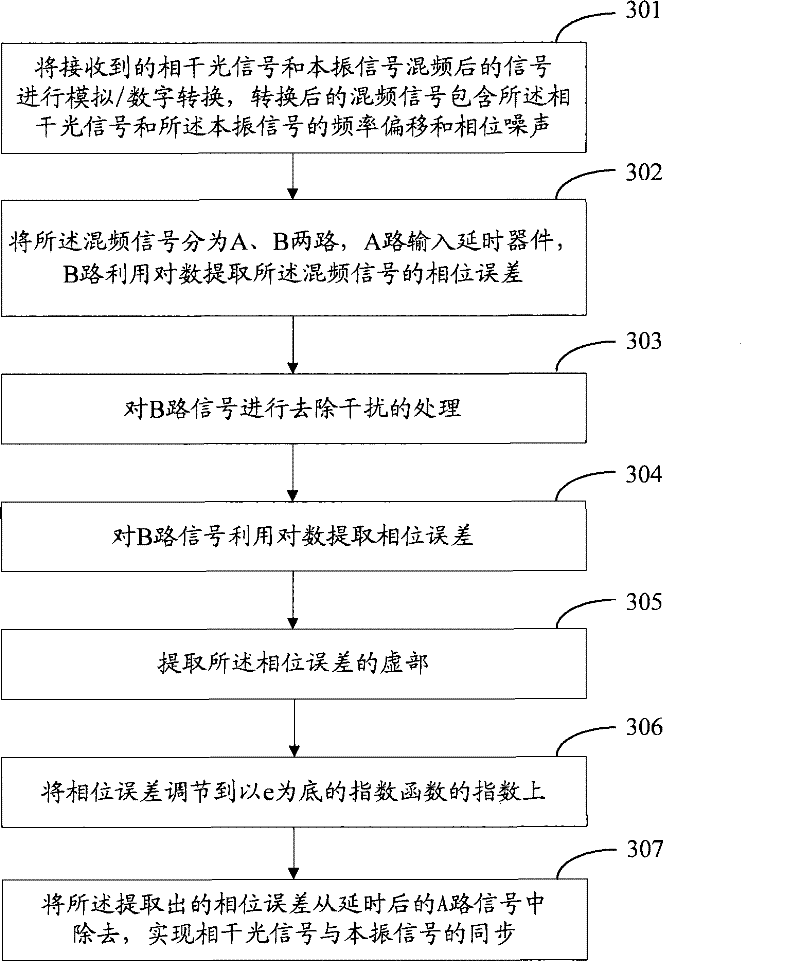
[0053] Embodiment three, refer to image 3 Detailed description, image 3 It is a schematic flow chart of the method in this embodiment.
[0054] Step 301: Perform analog / digital conversion on the mixed signal of the received coherent optical signal and the local oscillator signal, and the converted mixed signal contains the frequency offset and phase noise of the coherent optical signal and the local oscillator signal .
[0055] After frequency mixing, the received coherent optical signal and local oscillator signal are usually respectively input into the balanced receiver, and then the output signals of the balanced receiver are passed through the filter respectively, and the analog / digital conversion is performed, and the converted mixed frequency signal contains all frequency offset and phase noise of the coherent optical signal and the local oscillator signal. Let the received coherent optical signal be The local oscillator signal is Among them, m(t) is the noise s...
PUM
 Abstract
Description
Claims
Application Information
 - Generate Ideas
- Intellectual Property
- Life Sciences
- Materials
- Tech Scout
- Unparalleled Data Quality
- Higher Quality Content
- 60% Fewer Hallucinations
Browse by: Latest US Patents, China's latest patents, Technical Efficacy Thesaurus, Application Domain, Technology Topic, Popular Technical Reports.
© 2025 PatSnap. All rights reserved.Legal|Privacy policy|Modern Slavery Act Transparency Statement|Sitemap|About US| Contact US: help@patsnap.com


