Eureka AIR delivers breakthrough ideas for toughest innovation challenges, trusted by R&D personnel around the world.

Battery inspection system

A technology for inspection devices and batteries, which is applied in the directions of measuring devices, secondary battery manufacturing, and secondary battery repair/maintenance, etc., can solve the problems of shaking electrode contours, large amount of handover movement of batteries 102, and inability to increase inspection speed, etc. Check the effect of speed

Active Publication Date: 2010-06-09
TOSHIBA IT & CONTROL SYSTEMS CORP
View PDF3 Cites 31 Cited by
  • Summary
  • Abstract
  • Description
  • Claims
  • Application Information

AI Technical Summary

Problems solved by technology

[0019] Also, since the battery 102 has a large amount of transfer and movement, it takes time to transfer the battery 102, and the battery 102 at the inspection position P20 is subjected to vibration when the battery is clamped or taken out.
As a result, the contours of the electrodes in the battery 102 are shaken or interrupted, making it difficult to obtain a clear transmission image.
This also prevents the inspection speed from being improved

Method used


Image

  • Battery inspection system
  • Battery inspection system
  • Battery inspection system

Examples


Embodiment approach 1

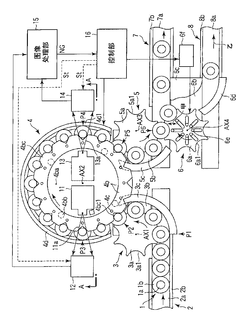
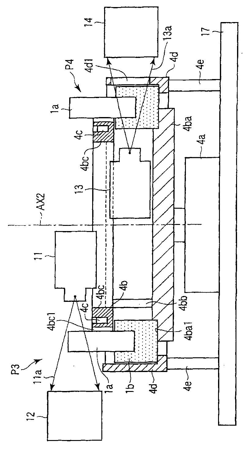
[0049] figure 1 and figure 2 is a composition diagram showing Embodiment 1 of the present invention, figure 1 is a top view, figure 2 yes figure 1 The A-A line shown is the sectional view.

[0050] The battery inspection device consists of a battery delivery system and a battery detection system.

[0051] The components of the battery conveying system include: conveying conveyor belt 2 for conveying batteries 1 in a specified direction, input mechanism 3, rotating conveying part 4, take-out mechanism 5, unqualified product take-out mechanism 6, qualified product conveying conveyor belt 7, and unqualified product conveying conveyor belt8.

[0052] The components of the battery inspection system include: the first X-ray source 11 and the first X-ray detector 12 for X-ray inspection on the upper side of the battery 1, the second X-ray source 13 and the first X-ray detector for X-ray inspection on the lower side of the battery 1 2. X-ray detector 14, image processing un...

Embodiment approach 2

[0133] Embodiment 2 (corresponding to claims 5 and 6)

[0134] Compared with Embodiment 1, Embodiment 2 differs in that the cylindrical table 4b is continuously rotated at a predetermined rotation speed and that X-ray detectors 12', 14' with shake correction functions are used instead of X-ray detectors 12, 14. The X-ray detectors 12', 14' with shake correction have a function of capturing a transmission image of a moving object without movement and shake.

[0135] Therefore, as Embodiment 2, except for the above two points, the configuration of Embodiment 1 can be applied as it is, so the description of the overall configuration of the battery inspection device will be omitted.

[0136] Figure 4 It is a configuration diagram (plan view) of the X-ray detectors 12', 14' with a shake correction function. Such X-ray detectors 12', 14' with shake correction are known from the laid-open publication (Japanese Unexamined Patent Publication No. 2003-114279).

[0137] Specifically...


PUM


Abstract

The subject of the invention is to improve checking speed and to obtain vivid transflective images. A battery checking device comprises an X ray source (11, 13) for irritating X ray to the battery (1) conveyed to the predetermined checking positions (P3, P4); an X ray detector (12, 14) for capturing X ray transmitted from the battery (1) and outputting the transflective images of the battery (1);and an image processing portion (15) for determining whether the electrode is qualified according to the transflective images each X ray detector (12, 14) captured, wherein the image processing portion includes grooves (4bc1) formed on the outer circumferential surface and having equal intervals therebetween and a cylindrical table (4b) for adhering adhesion units (4c) of the batteries (1) throwninto these grooves (4bc1); and a rotary transmission portion (4) of the rotation mechanism (4a) making the battery (1) of grooves (4bc1) adhered to the cylindrical table (4b) rotate along the circular rail and be delivered to the checking positions (P3, P4), wherein the battery (1) is adhered to the groove (4bc1) of the cylindrical table (4b) for the rotary delivery, while the transflective images are captured sequentially at the checking position and whether the image is qualified is determined.

Description

technical field [0001] The present invention relates to a battery inspection device that irradiates X-rays and takes images of the X-rays penetrating the battery to inspect the internal state of the battery. Background technique [0002] Lithium-ion batteries are wound in several layers with separators sandwiched between the positive and negative electrode sheets to form a cylindrical shape and housed in a cylindrical container, then take out the lead wires for taking electricity from each electrode sheet . The end of the lead wire to be the positive electrode is welded to the sealing member, and the end of the lead wire to be the negative electrode is welded to the bottom of the cylindrical container, etc., and electrolyte solution is injected into the cylindrical container and sealed to complete the battery. [0003] Since this lithium ion battery forms a cylindrical shape by winding the positive electrode sheet and the negative electrode sheet in several layers, there is...

Claims


Application Information

Patent Timeline
IPC IPC(8): H01M10/04B65G47/80G01B15/00
CPCY02E60/12Y02E60/10Y02P70/50G01N23/04G01N23/083G01N23/223H01M10/42
Inventor 染谷幸夫长峰利行玉木清英相岛道秋筱原正治
Owner TOSHIBA IT & CONTROL SYSTEMS CORP
Why Eureka
Eureka Blog
Learn More