Solution dehumidifier

A solution dehumidification and concentrated solution technology, applied in heating methods, lighting and heating equipment, applications, etc., can solve the problems of high energy consumption, loud noise, and slow dehumidification speed, and achieve low energy consumption, low noise, and fast dehumidification speed Effect

Inactive Publication Date: 2010-06-09
LG ELECTRONICS (TIANJIN) APPLIANCES CO LTD
View PDF0 Cites 1 Cited by
  • Summary
  • Abstract
  • Description
  • Claims
  • Application Information

AI Technical Summary

Problems solved by technology

[0006] However, the dehumidifiers in the prior art have relatively high noise, high energy consumption and slow dehumidification speed due to the compressor.

Method used


Image

  • Solution dehumidifier
  • Solution dehumidifier
  • Solution dehumidifier

Examples


Embodiment Construction

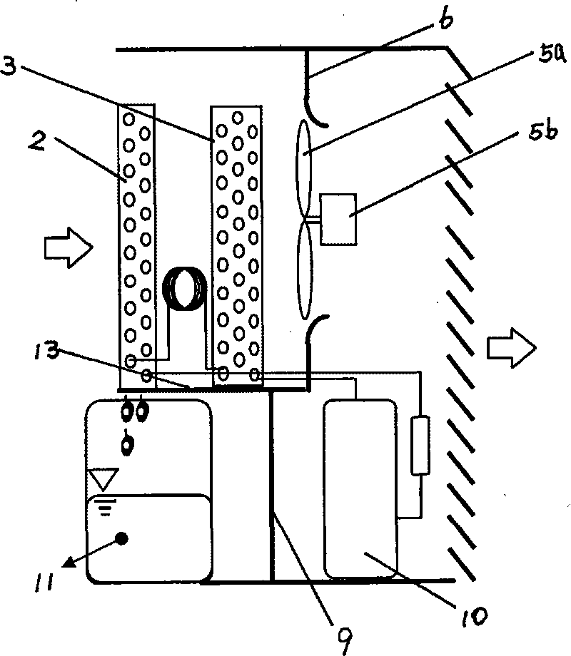
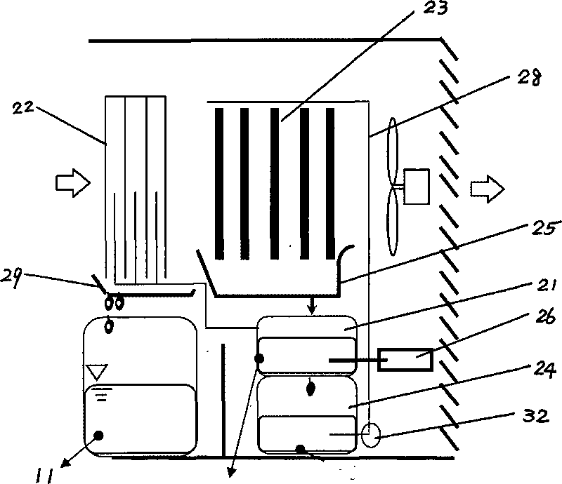
[0022] Below in conjunction with accompanying drawing and specific embodiment the present invention is described in further detail:

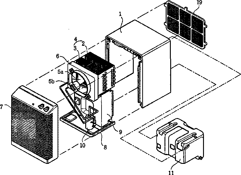
[0023] Such as image 3 , 4 As shown, the solution dehumidifier of the present invention includes: a casing formed with an air inlet and an air outlet; the air sucked through the air inlet is sequentially heat-exchanged, and the set is composed of an evaporator and a condenser The heat exchanger is housed in the casing, the water receiving bucket 11 that stores the condensed water that falls from the surface of the evaporator, the blower fan and the motor 5 that suck the air in the room into the inside of the casing and discharge it to the room , the evaporator is a condenser 22 with water vapor flowing inside, and the condenser is a wet wood device composed of a liquid storage tank 32 and multiple rows of solid wooden strips 33 hanging below the liquid storage tank 32 23. There are a plurality of through holes 31 on the bottom surface of the ...


PUM


Abstract

The invention discloses a solution dehumidifier. An evaporator is a cryophorus with water vapor flowing inside; a condenser is a wet wood device comprising a liquid storage tank and a plurality of rows of solid wood slats; a condenser water-containing plate is arranged below the wet wood device; a dilute solution tank for providing the water vapor for the condenser is arranged below the condenser water containing plate; a concentrated solution tank is arranged below the dilute solution tank; a heater is arranged in the dilute solution tank; the dilute solution tank is communicated with the concentrated solution tank; the flow of the solution from the dilute solution tank to the concentrated solution tank is controlled by a throttle valve; the concentrated solution tank is connected with the liquid storage tank at the upper part through a connecting pipe; and a pump pumping the concentrated solution in the concentrated solution tank to the liquid storage tank is arranged on the connecting pipe. In the invention, lithium chloride or lithium bromide solution is utilized for rapid dehumidification so that the heat consumption power is low. The wet wood device is designed, thereby the contact area is large, the adsorption is full, the dehumidification is complete, and the overall efficiency is enhanced.

Description

technical field [0001] The invention relates to a dehumidifier, in particular to a solution dehumidifier which utilizes solution to quickly dehumidify. Background technique [0002] Such as figure 1 , 2 As shown, the dehumidifier in the prior art includes: a casing 1 that constitutes the appearance of the left and right sides and the top, and the front, rear and bottom surfaces are open; the evaporator 2 and the condenser 3 that are arranged inside the casing 1 The heat exchanger 4 for dehumidification; the compressor 10 for compressing the refrigerant circulating in the evaporator 2 and the condenser 3; it is arranged in front or behind the heat exchanger 4 and generates wind power to suck the indoor air into the casing 1 and then discharged to the indoor blower fan 5a and motor 5b; arranged in front of the casing 1, so that the dehumidified air flowing through the heat exchanger 4 is discharged to the outside of the front panel 7 formed with a grid; arranged in The bott...

Claims


Application Information

Patent Timeline
Patent Type & Authority Applications(China)
IPC IPC(8): F24F3/14B01D53/26
Inventor 卢大为
Owner LG ELECTRONICS (TIANJIN) APPLIANCES CO LTD
Why Eureka
Try Eureka