
Plane spiral inductor

A flat spiral, inductive technology, applied in the direction of inductors, fixed inductors, fixed signal inductors, etc., can solve the problems of metal conductor loss, the reduction of the quality factor Q of the inductor, etc., to reduce the series resistance, increase the Q value, and improve the performance. Effect

Inactive Publication Date: 2010-06-02
EAST CHINA NORMAL UNIV +1
View PDF3 Cites 15 Cited by
  • Summary
  • Abstract
  • Description
  • Claims
  • Application Information

AI Technical Summary

Problems solved by technology

[0011] The present invention aims to solve the technical problem that the quality factor Q of the inductance is reduced due to the metal conductor loss in the planar spiral inductor structure in the prior art

Method used


Image

  • Plane spiral inductor
  • Plane spiral inductor
  • Plane spiral inductor

Examples


Embodiment Construction

[0022] In order to make the technical features of the present invention more comprehensible, specific embodiments are given below in conjunction with the accompanying drawings to further describe the present invention.

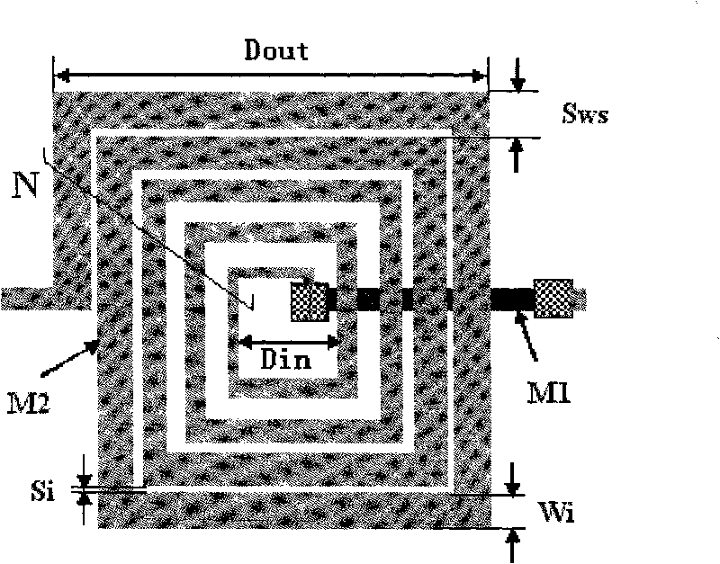
[0023] See figure 2 , which is a top view of the structure of the planar spiral inductor provided by an embodiment of the present invention.

[0024] The planar spiral inductor, the width w of the wire of the inductor coil i gradually increases from inside to outside, and the spacing between the wires of the inductor coil s i It gradually decreases from the inner ring to the outer ring. The sum of the width of the wire and the spacing between the corresponding adjacent wires is a certain value S ws . The ratio of the width of the wire to the spacing between its corresponding adjacent wires R wsi It gradually increases from the inner ring to the outer ring.

[0025] In this embodiment, the width value w of each coil of wire i (i=1, 2...n, where n is the...


PUM

PropertyMeasurementUnit
widthaaaaaaaaaa

Abstract

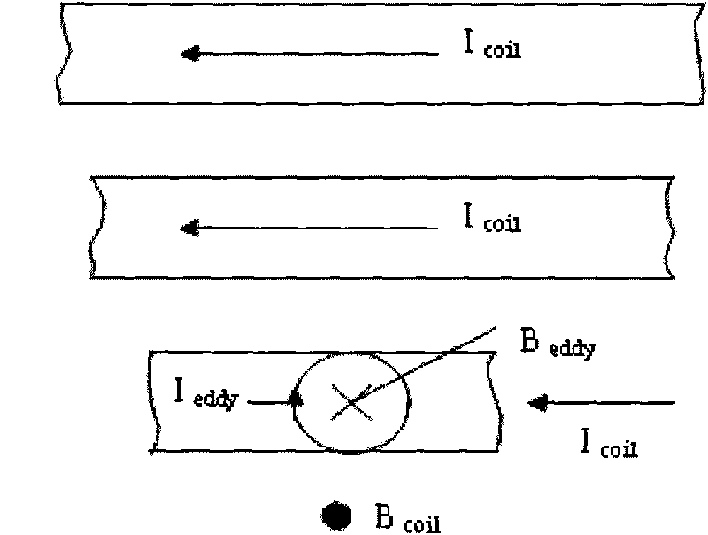
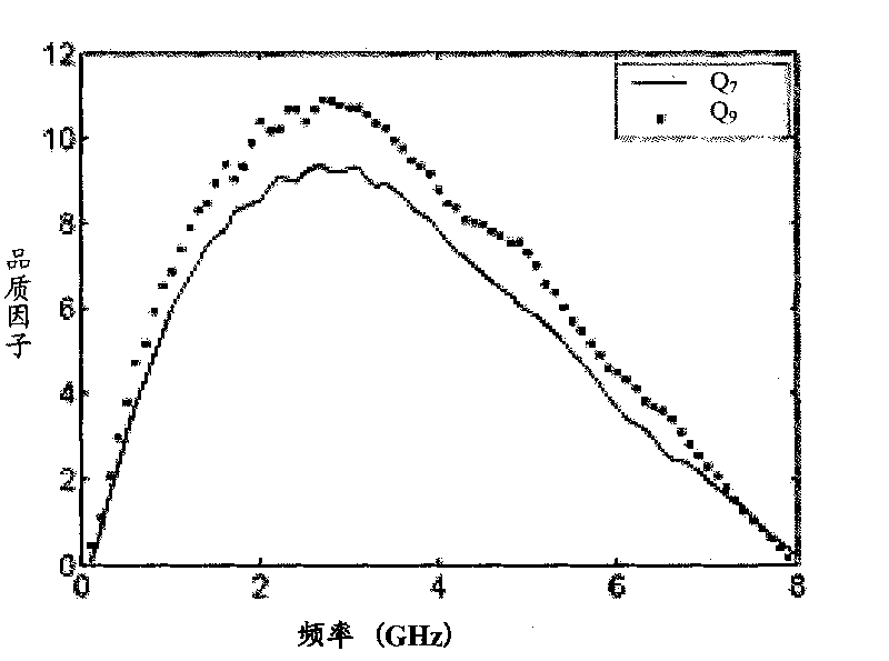
The invention discloses a plane spiral inductor; the width of a lead wire of the plane spiral inductor is gradually increased from interior to exterior, the distance between the lead wires is gradually reduced from an inner ring to an outer ring; compared with the inductor with the traditional structure, eddy effect and proximity effect of the plane spiral inductor are reduced at high frequency, the series resistance of inductor coil lead wires is reduced, so as to improve the quality factor Q value of the inductor on the premise of not changing the domain area and the size of inner diameter; a preparation process of the plane spiral inductor is compatible to the conventional CMOS process, and the performance of an important functional unit at the CMOS radio-frequency front end can be improved.

Description

technical field [0001] The invention relates to the technical field of semiconductor manufacturing, in particular to a planar spiral inductor. Background technique [0002] In the development of CMOS radio frequency integrated circuits (RFICs), the most urgent and difficult thing is to develop new high-performance devices and new unit circuits, which are the basis for realizing monolithic CMOS integrated RF front-ends. As a key component in radio frequency integrated circuits, planar spiral inductors are the most difficult components to design and master in circuits, and their performance parameters directly affect the performance of radio frequency integrated circuits. The on-chip inductor can realize the integration of the inductor in the radio frequency integrated circuit, thus contributing to the realization of the system on chip of the radio frequency integrated circuit. [0003] Most of the on-chip planar spiral inductors are wound on silicon substrates by metal films...

Claims


Application Information

Patent Timeline
Patent Type & Authority Applications(China)
IPC IPC(8): H01F37/00H01L27/00
Inventor 李曦刘婧石艳玲丁艳芳丁铨王勇陈寿面赵宇航
Owner EAST CHINA NORMAL UNIV
Learn More