Eureka AIR delivers breakthrough ideas for toughest innovation challenges, trusted by R&D personnel around the world.

Automatic wall-forming device and method of static pressure continuous concrete wall

An underground diaphragm wall and automatic wall forming technology, which is applied to underwater structures, water conservancy projects, artificial islands, etc., can solve problems such as high price support, environmental pollution, and poor comprehensive economy

Active Publication Date: 2010-06-02
QINGDAO JINGLI ENG
View PDF3 Cites 20 Cited by
  • Summary
  • Abstract
  • Description
  • Claims
  • Application Information

AI Technical Summary

Problems solved by technology

The existing underground diaphragm wall has superior support performance, but its price is high compared with cast-in-place piles, steel sheet piles, or cement-soil piles and other support forms, the construction is relatively difficult, the construction period is relatively long, and waste mud treatment is difficult, which is harmful to the environment. A certain degree of pollution, it is difficult to form a wall in saturated clay, silty clay, and confined water soil layer, the wall bearing capacity is low, and the comprehensive economy is not good

Method used


Image

  • Automatic wall-forming device and method of static pressure continuous concrete wall
  • Automatic wall-forming device and method of static pressure continuous concrete wall
  • Automatic wall-forming device and method of static pressure continuous concrete wall

Examples


Embodiment

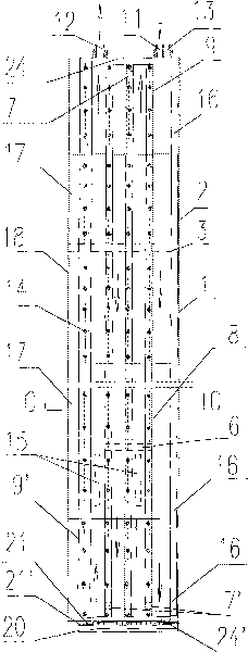
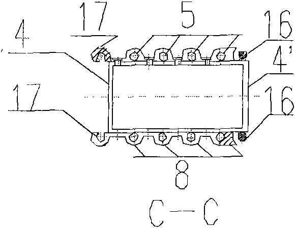
[0016]The automatic wall-forming device of this embodiment consists of three parts: basic body, docking body, and valve group; its basic body part includes basic section 1, connecting section 2, wedge-shaped interface 3, short side surface 4, and short side surface 4' , main channel 5, cable cross channel 6, cooling water circulation channel 7, cooling water circulation channel 7', corrugated plate 8, top corrugated plate 9, end corrugated plate 9', sealing strip 10, water inlet joint 11, water outlet Connector 12, cable inlet 13, connecting screw 14, vibrator 15, connecting corrugated plate 18, upper blocking 24 and lower blocking 24'; main functions are: 1, the main body of force and force transmission, 2, the mixture carrier and Wall section shape mold, 3. Butt joint body and valve group parts placement base; the long side of the basic body section is 300mm-1200mm, the short side is 100mm-1000mm, and its surface shape has a combined trapezoidal plate shape, thick-walled stra...


PUM


Abstract

The invention belongs to the technical field of buildings, relating to an automatic wall-forming device and method of static pressure continuous concrete wall used for anti-seepage, water interception and retaining occasions such as deep foundation pit, tunnel and riverbank; the existing full hydraulic static pile machine is used as a host machine; two automatic wall-forming device combinations mutually associated and respectively independently moved having wave-shaped sections can be clamped simultaneously; the surface shape of the wave-shaped plate and the rectangle inside casing are used as references, and the two short outer edges thereof are respectively provided with connectors having specific guiding limit function; the automatic wall-forming device provided with a double-open type valve at the end part thereof is internally pre-hung with a steel reinforcement cage; concrete is filled sequentially, and the wall-forming device is pressed into a preset thickness of soil layer one by one; one of the wall-forming device combination is lifted, and simultaneously a high frequency vibrator installed in a wave-shaped body is started; a reinforced concrete unit wall sections are formed by vibrating and lifting the wall-forming device; and the device and method has novel technology, good environmental protection effect, reliable quality, high bearing capacity, board applicability and short construction period.

Description

Technical field: [0001] The invention belongs to the technical field of foundation construction in the building industry, and relates to a static pressure underground continuous wall automatic wall forming device and method for complex deep foundation pits, tunnels, embankments and other engineering projects for soil retaining, seepage prevention and water interception. Background technique: [0002] Reinforced concrete underground diaphragm wall (referred to as underground diaphragm wall) is used as the supporting wall of complex deep foundation pits, subways, and tunnel excavation support systems. It has high rigidity, high strength, good integrity, and good durability and impermeability. Features: In addition to being used as a foundation pit support structure and having the function of water interception and anti-seepage, it is often used as a building load-bearing structure together with the underground main structure. The existing underground diaphragm wall constructio...

Claims


Application Information

Patent Timeline
Patent Type & Authority Applications(China)
IPC IPC(8): E02D29/02
Inventor 欧阳甘霖张明义邓洪亮寇海磊殷作鹏
Owner QINGDAO JINGLI ENG
Why Eureka
Eureka Blog
Learn More