
Large vertical centrifugal casting machine

A vertical centrifugal casting machine technology, applied in the field of centrifugal casting machines, can solve the problems of no temperature measuring mechanism, inability to produce castings, structural limitations, etc., and achieve the effects of reducing labor intensity, ensuring pouring quality, and good performance

Inactive Publication Date: 2010-06-02
TIANSHUI HUARONG CASTING MACHINERY
View PDF0 Cites 8 Cited by
  • Summary
  • Abstract
  • Description
  • Claims
  • Application Information

AI Technical Summary

Problems solved by technology

[0002] There are many key problems in the vertical centrifugal casting machine used in the current industrial production: 1. The main machine has no vibration monitoring device, so it is impossible to grasp the vibration situation of the main machine when it is working, and it is impossible to grasp the possible accidents caused by the vibration of the equipment; 2. The bearing on the main shaft does not have a temperature measuring mechanism and a cooling device, and the bearing on the main shaft has a temperature rise due to a large load, and the temperature rise cannot be grasped and the temperature has not been lowered, so the normal operation of the equipment cannot be effectively guaranteed; 3. There is no The temperature measurement system cannot monitor the temperature in the mold cylinder before pouring and the temperature change during the solidification process of the poured molten metal online, so the quality of the poured product cannot be guaranteed; 4. Due to structural limitations, small specifications, and no monitoring and adjustment system mentioned above, Only castings with a diameter of less than 2000mm can be produced, and castings with a diameter greater than 2000mm cannot be produced, which is far from meeting the needs of modern industrial production

Method used


Image

  • Large vertical centrifugal casting machine
  • Large vertical centrifugal casting machine
  • Large vertical centrifugal casting machine

Examples


specific Embodiment approach

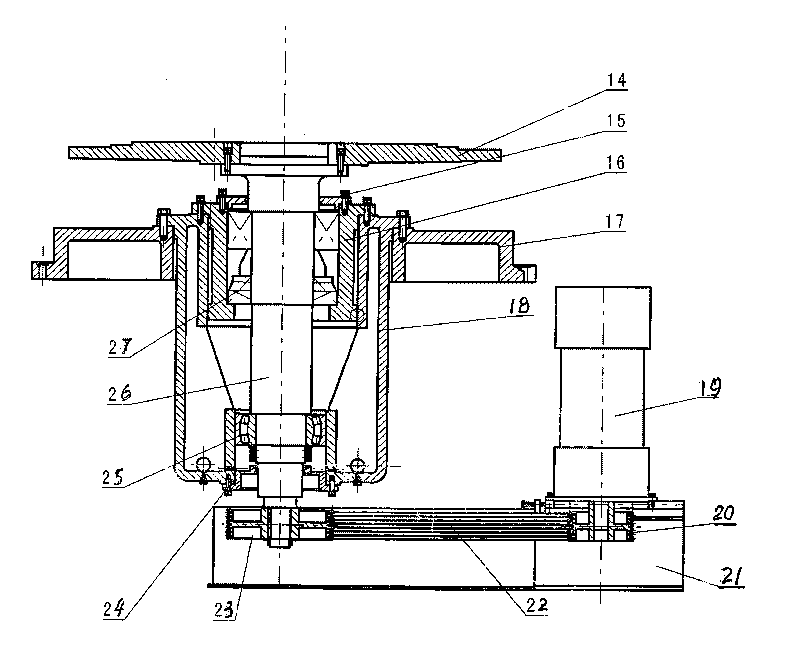
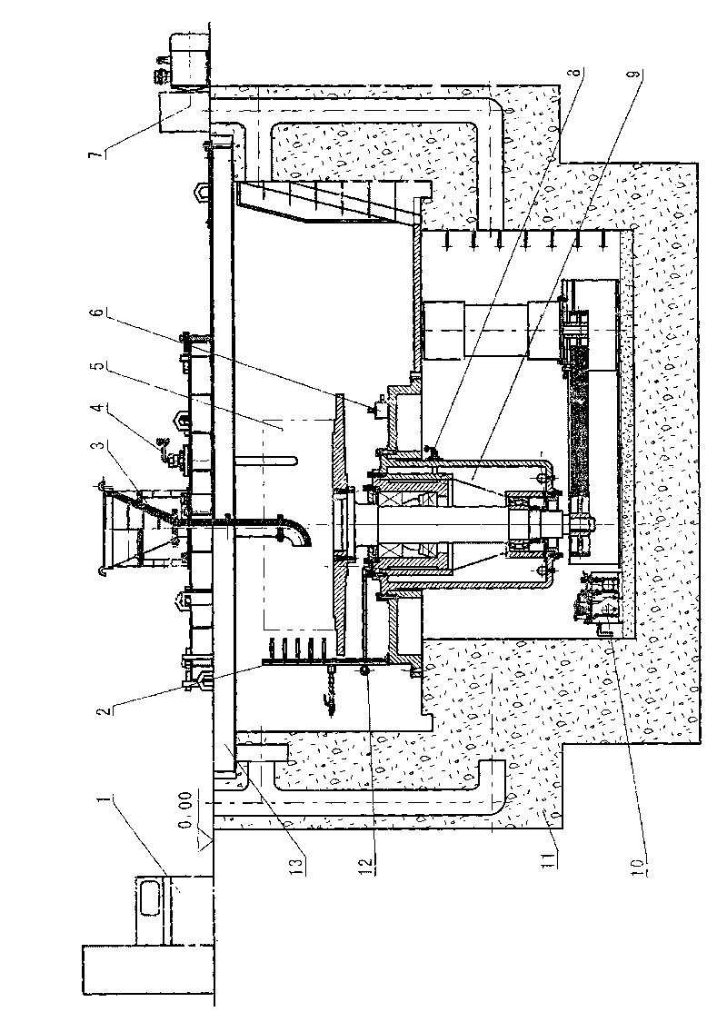
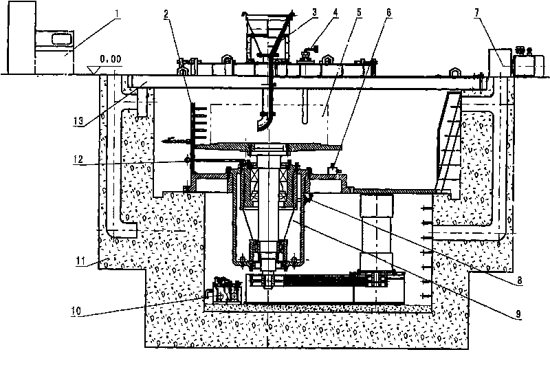
[0016] The specific embodiment of the present invention will be described below in conjunction with the accompanying drawings: the large vertical centrifugal casting machine consists of a main engine, a main motor, a temperature measuring system in a mold, a mold cooling system, a pouring system, a vibration measuring mechanism, a bearing temperature measuring system, a bearing cooling system, Lubrication system, air induction system, protection system and electrical control system, such as figure 1 As shown, the main engine 9 is placed in the pit, and the main engine base 17 is installed on the platform of the equipment installation foundation 11 and fixed with bolts, as figure 2 Shown, casing 18 is installed on the support 17 of main frame 9, is fixed with bolt, and inlay 16 is housed in casing 18, is fixed with bolt, and upper bearing 27 is installed in the inlay 16, and lower bearing 25 is installed in casing 18 bottoms, The main shaft 26 is installed in the bearing, and ...


PUM

PropertyMeasurementUnit
diameteraaaaaaaaaa
diameteraaaaaaaaaa

Abstract

The invention discloses a large vertical centrifugal casting machine which is one of centrifugal casting machines. By a reasonable host machine structure and the cooperative working of temperature measuring, vibration measuring, cooling and advanced automatic control systems, the defect of the traditional centrifugal casting machine is overcome, the comprehensive performance of the whole machine is improved, and the safety, the reliability and the carrying capacity are improved, thereby a high-quality casting with a large size can be produced. The machine comprises a host machine, a main motor, a die internal temperature measuring and cooling system, a bearing temperature measuring and cooling system, a pouring system, a vibration measuring mechanism, a lubricating system, an air inducing system, a protecting system and an electrical appliance control system, wherein the host machine is installed on an equipment installation foundation in a pit; the upper end of a main shaft is provided with a die flange, and the lower end is connected with the main motor by a belt wheel and a drive belt. A pouring process curve can be arranged at will and automatically traced, and a host machine die has stepless smooth speed regulation. The machine is used for industries of steel, electricity, petroleum, nuclear engineering, and the like to cast a large roller ring, a nonferrous metal sleeve part and a special shape element.

Description

technical field [0001] The invention relates to a centrifugal casting machine, in particular to a large vertical centrifugal casting machine. Background technique [0002] There are many key problems in the vertical centrifugal casting machine used in the current industrial production: 1. The main machine has no vibration monitoring device, so it is impossible to grasp the vibration situation of the main machine when it is working, and it is impossible to grasp the possible accidents caused by the vibration of the equipment; 2. The bearing on the main shaft has no temperature measuring mechanism and cooling device, and the bearing on the main shaft has a temperature rise due to the large load, and the temperature rise cannot be grasped and the temperature has not been lowered, so the normal operation of the equipment cannot be effectively guaranteed; 3. There is no The temperature measurement system cannot monitor the temperature in the mold cylinder before pouring and the t...

Claims


Application Information

Patent Timeline
Patent Type & Authority Applications(China)
IPC IPC(8): B22D13/00B22D13/12
Inventor 崔岗万小宁李建平王建升张立娟马丽丽
Owner TIANSHUI HUARONG CASTING MACHINERY
Learn More