
Longitudinal shaft assembly for a motor vehicle

A longitudinal axis, automotive technology, used in controls, couplings, shafts and bearings, etc.

Active Publication Date: 2010-05-26
GKN DRIVELINE DEUTSCHLAND GMBH
View PDF0 Cites 4 Cited by
  • Summary
  • Abstract
  • Description
  • Claims
  • Application Information

AI Technical Summary

Problems solved by technology

Therefore, in particular, it must be avoided that parts of the longitudinal axis device penetrate the passenger compartment and / or the fuel tank, whereby an additional risk of injury to vehicle occupants or a risk of fire from leaking fuel could occur

Method used


Image

  • Longitudinal shaft assembly for a motor vehicle
  • Longitudinal shaft assembly for a motor vehicle
  • Longitudinal shaft assembly for a motor vehicle

Examples


Embodiment Construction

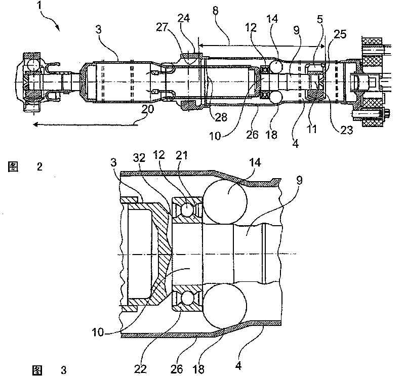
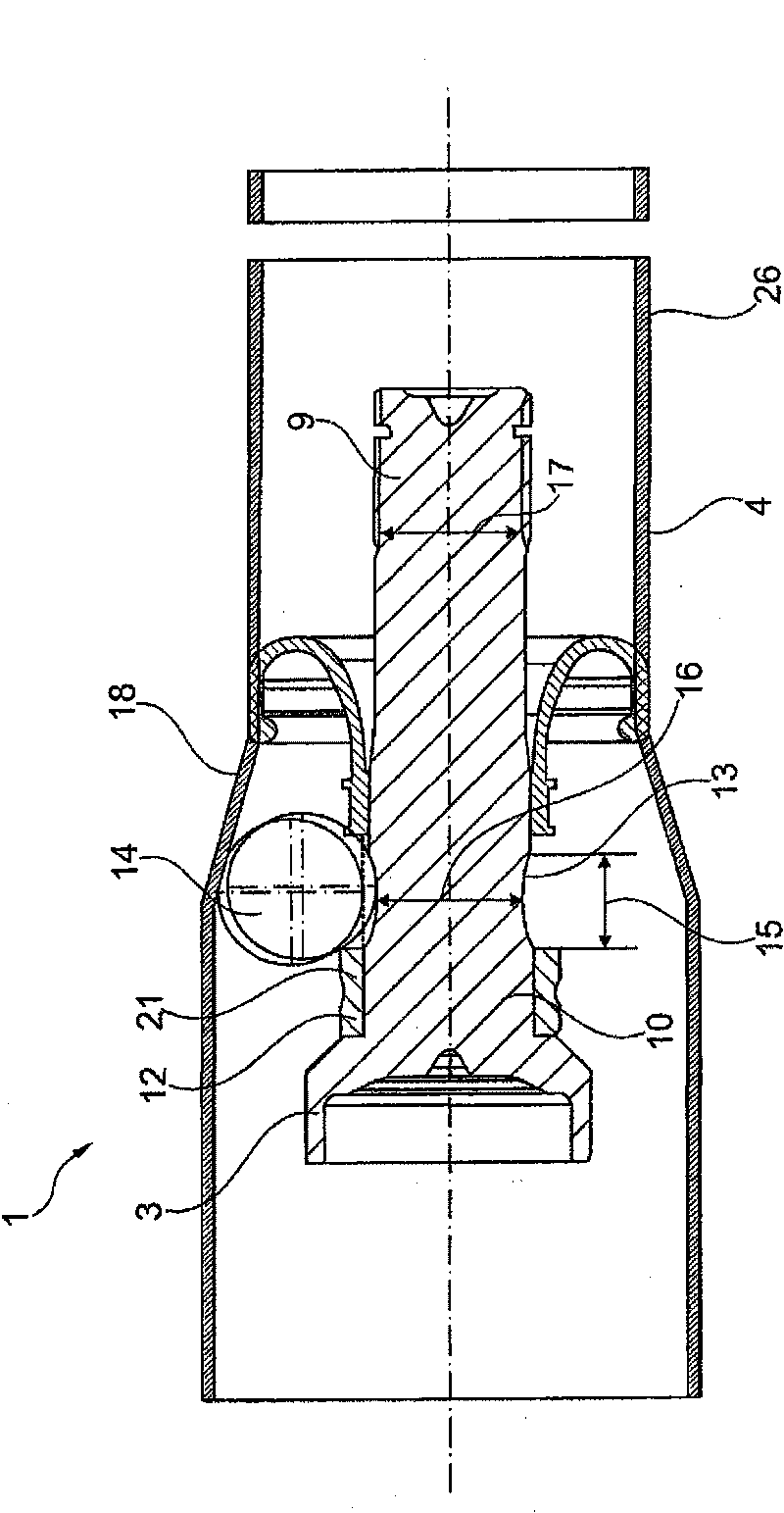
[0025] figure 1 The longitudinal axis device 1 of a motor vehicle 2 is shown, the direction of travel 20 of the motor vehicle 2 is in figure 1 The lower part is shown. The longitudinal axis device 1 consists at least of a first shaft 3 and a second shaft 4, which are connected to each other via a spherical synchronous joint 5, here in the form of an axial joint shown in the middle. Offsetable joints ("moving joints"). The first axis 3 itself consists of several components, which are in figure 1 clearly visible in. In particular, on the first shaft 3 there is an additional spherical synchronous joint arranged on the pin of the first shaft 3, as figure 1 shown on the left. Arranged at the other end of the first shaft 3 is a pin 9 which extends into a ball-shaped synchronous joint of the longitudinal shaft arrangement 1 . This bolt 9 is connected at its first end to the joint inner element 23 of the ball synchronous joint 5 on the one hand via its second end 11 and on the o...


PUM


Abstract

A longitudinal shaft assembly for a motor vehicle, comprising at least a first shaft and a second shaft, a ball-type constant velocity joint for connecting the first shaft to the second shaft and at least one central bearing for supporting the longitudinal shaft assembly with respect to a body of the motor vehicle.

Description

technical field [0001] The invention relates to a longitudinal shaft arrangement for a motor vehicle, wherein at least a first shaft and a second shaft are provided, said first shaft and a second shaft being connected to each other by means of spherical synchronous joints in order to connect the drive input side of the motor vehicle to the drive output side. The longitudinal axis device is generally used to transmit the driving force from the driving device (such as the engine and / or transmission) of the automobile to the driven device (such as the differential, shaft reducer, transmission), the longitudinal axis device extends in the direction of the vehicle, And the longitudinal axis device transmits the driving force to the rear wheels when the driving device is installed in the front area of ​​the vehicle, and transmits the driving force to the front wheels when the driving device is arranged in the rear area. Background technique [0002] The longitudinal axle assembly...

Claims


Application Information

Patent Timeline
IPC IPC(8): B60K17/22
CPCF16D2300/22B60K17/22F16D3/223F16D2003/22309Y10S464/906F16C7/02
Inventor W·洛贝尔S·莱曼F·普弗兰泽
Owner GKN DRIVELINE DEUTSCHLAND GMBH
Learn More