
Ultrasonic testing method for steel pipe void

An ultrasonic testing and steel pipe technology, which is applied in the direction of using sonic/ultrasonic/infrasonic waves to analyze solids, etc., can solve problems such as imperfect specifications and procedures, inability to intuitively reflect concrete and steel pipe walls, and no work flow, so as to save manpower. Effect

Inactive Publication Date: 2010-05-19
JIANGSU TRANSPORTATION RES INST CO LTD
View PDF0 Cites 15 Cited by
  • Summary
  • Abstract
  • Description
  • Claims
  • Application Information

AI Technical Summary

Problems solved by technology

[0002] The compactness of the concrete inside the steel tube of a concrete-filled steel tube arch bridge directly affects the compressive capacity of the steel tube arch. Due to the construction technology of the steel tube concrete, the concrete inside the tube after pouring is concealed and cannot be directly observed by the naked eye. Whether there is a gap between the concrete and the steel tube wall The void defects cannot be reflected intuitively.
As far as the current non-destructive testing methods are concerned, small hammer knocking and ultrasonic methods are more commonly used. Ultrasonic testing is to detect whether the concrete and the inner wall of the steel pipe are empty, whether there is space inside the concrete, and the compactness of the concrete in the steel pipe. The existing ultrasonic method, because the relevant specifications and procedures are still far from perfect, there is no specific workflow to guide the specific detection, which will make the detection greatly affected by human factors

Method used


Image

  • Ultrasonic testing method for steel pipe void
  • Ultrasonic testing method for steel pipe void
  • Ultrasonic testing method for steel pipe void

Examples


Embodiment 1

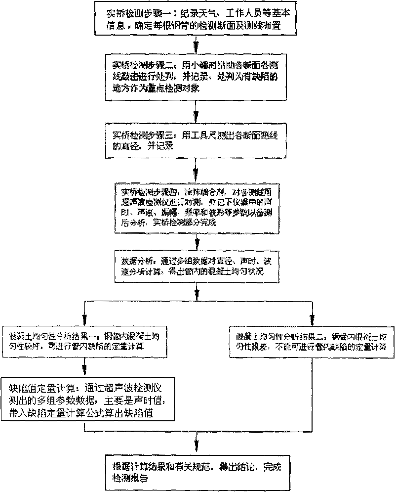
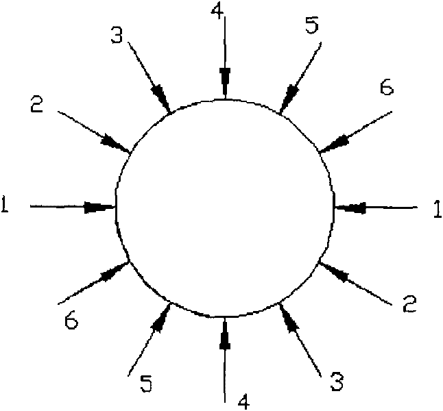
[0023] Step 1 Determine the detection section of each steel pipe, and set several measuring lines on the steel pipe surface, each measuring line is distributed at both ends of the diameter of the steel pipe section, and each measuring line is evenly distributed on the steel pipe surface, as figure 2 shown.

[0024] Step 2 Use a small hammer to knock on each measuring line of each section of the arch rib, and make a preliminary judgment on the compactness of the concrete in the steel pipe according to the knocking sound, and record the judgment results, and take the places with defects as the key detection objects;

[0025] Step 3 Measure the diameter of each section measuring line with a tool ruler, and record it;

[0026] Step 4 Apply coupling agent on the surface of the steel pipe, measure each measuring line with an ultrasonic detector, and record the sound time, sound velocity, amplitude, frequency and waveform parameters displayed in the instrument;

[0027] Step 5 anal...


PUM


Abstract

The invention relates to an ultrasonic testing method for steel pipe void, which comprises the following steps of: confirming a tested fracture surface of each steel pipe and arranging a plurality of survey lines on the surface of each steel pipe in a uniform distribution way; knocking each survey line on each fracture surface of arch ribs by a small hammer, preliminarily judging the compaction rate of concretes inside the steel pipe according to the knock, and recording judging results; measuring diameters of the survey lines on each fracture surface by using a tooling scale and recording; coating a coupling agent on the surface of each steel pipe, detecting each survey line by using an ultrasonic detector, and recording parameters of sound time, sound velocity, amplitude and wave form which are displayed in the detector; analyzing and calculating the recorded multi-group data to obtain the uniformity state of the concretes inside the steel pipes; if the uniformity state is favorable, then carrying out a quantitative calculation on inner pipe defects, and working out an inner pipe defect value of each fracture surface through a sound time value detected by the ultrasonic detector; and if the uniformity state is unfavorable, then obtaining a detection conclusion.

Description

technical field [0001] The invention belongs to the field of bridge structures, and in particular relates to an ultrasonic detection method for voiding of steel pipes. Background technique [0002] The compactness of the concrete inside the steel tube of a concrete-filled steel tube arch bridge directly affects the compressive capacity of the steel tube arch. Due to the construction technology of the steel tube concrete, the concrete inside the tube after pouring is concealed and cannot be directly observed by the naked eye. Whether there is a gap between the concrete and the steel tube wall None of the void defects can be reflected intuitively. As far as the current non-destructive testing methods are concerned, small hammer knocking and ultrasonic methods are more commonly used. Ultrasonic testing is to detect whether the concrete and the inner wall of the steel pipe are empty, whether there is space inside the concrete, and the compactness of the concrete in the steel pip...

Claims


Application Information

Patent Timeline
Patent Type & Authority Applications(China)
IPC IPC(8): G01N29/04G01N29/07
Inventor 傅斌张宇峰朱晓文康俊
Owner JIANGSU TRANSPORTATION RES INST CO LTD
Learn More