Vacuum superconducting electric heater and manufacturing method thereof
A superconducting and vacuum technology, applied in heating methods, electric heating systems, space heating and ventilation, etc., can solve the problems of low heat dissipation efficiency and small heat dissipation area of vacuum superconducting heaters, so as to improve heat dissipation efficiency and heating effect , the effect of increasing the relative surface area
- Summary
- Abstract
- Description
- Claims
- Application Information
AI Technical Summary
Problems solved by technology
Method used
Image


Examples
Embodiment 1
[0024] figure 2 The front view of the vacuum superconducting heater provided by Embodiment 1 of the present invention, image 3 It is a schematic diagram of the structure of the heat sink in the vacuum superconducting heater provided by Embodiment 1 of the present invention, Figure 4 The top view of the vacuum superconducting heater provided by Embodiment 1 of the present invention, Figure 5 for image 3 A-A in the sectional view. like figure 2 , 3 , 4, and 5, the present embodiment provides a vacuum superconducting heater, including a heating rod 3 and a heat sink 1. The two cover sheets 4, the grooves 5 on the two cover sheets 4 form a heat conduction chamber 6 after fastening; the cover sheets 4 are respectively formed with multiple grooves 5, and the heat sink 1 is formed with multiple grooves after fastening. Heat conduction cavity 6 ; the edges of the two cover sheets 4 are welded to each other, and multiple heat conduction cavities 6 on each heat sink 1 commun...
Embodiment 2
[0030] Image 6 It is the front view of the vacuum superconducting heater provided by the second embodiment of the present invention. like Image 6 As shown, the present embodiment can be based on the above-mentioned embodiment one, and the difference is that a connecting pipe 7 is also arranged between adjacent cooling fins 1 in the vacuum superconducting heater, and the two ends of the connecting pipe 7 are respectively connected to the adjacent The outer portions of the interfaces 2 of the two heat sinks 1 are connected by soldering so as to connect adjacent heat sinks 1 . The heat conduction cavities 6 of the heat sinks 1 are connected through the connecting pipe 7, and the connecting pipe 7 preferably has a length ranging from 2 centimeters (cm) to 2.5 cm.
[0031] The technical solution of this embodiment further solves the problem of possible gas leakage at the connection of the heat sink 1 by welding the connecting pipe 7 to the interface 2 of the adjacent heat sink ...
Embodiment 3
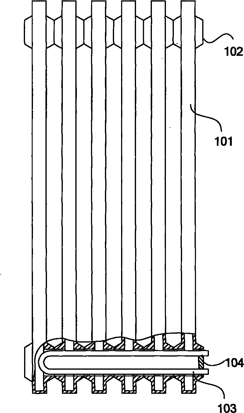
[0035] Figure 7 The front view of the vacuum superconducting heater provided for the third embodiment of the present invention. like Figure 7As shown, this embodiment can be based on the above-mentioned embodiment one or embodiment two, and the difference is that: the vacuum superconducting heater is also provided with a sleeve 8, and the sleeve 8 is set in the continuous connecting pipes 7, In particular, the connecting pipes 7 pierced at the bottom of the heat sink 1 , the heating rod 3 is inserted into the casing 8 ; .
[0036] In the technical solution of this embodiment, the heating rod 3 can be separated from the heat conduction cavity 6 by setting the sleeve 8 and inserting the heating rod 3 into the sleeve 8 . During the use of the vacuum superconducting heater, the use of the heating rod 3 has a certain life, and its life is often shorter than that of the electric heater, and the heating rod 3 needs to be replaced after a period of use. Since the heating rod 3 i...
PUM
| Property | Measurement | Unit |
|---|---|---|
| Length | aaaaa | aaaaa |
Abstract
Description
Claims
Application Information
 - R&D
- Intellectual Property
- Life Sciences
- Materials
- Tech Scout
- Unparalleled Data Quality
- Higher Quality Content
- 60% Fewer Hallucinations
Browse by: Latest US Patents, China's latest patents, Technical Efficacy Thesaurus, Application Domain, Technology Topic, Popular Technical Reports.
© 2025 PatSnap. All rights reserved.Legal|Privacy policy|Modern Slavery Act Transparency Statement|Sitemap|About US| Contact US: help@patsnap.com