
Fiber optic gyro coil wound by square section preformed fibers

A technology of fiber optic gyroscope and cross-section, which is applied in the direction of Sagnac effect gyroscope to achieve the effect of improving operability

Inactive Publication Date: 2010-05-12
ZHEJIANG UNIV
View PDF0 Cites 3 Cited by
  • Summary
  • Abstract
  • Description
  • Claims
  • Application Information

AI Technical Summary

Problems solved by technology

[0009] In view of the fact that the existing fiber optic gyro coil processing methods cannot effectively solve the problems of coil vibration temperature sensitivity and fiber torsion and "sag", the purpose of the present invention is to provide a fiber optic gyro coil made of prefabricated optical fibers with square cross-sections. Effectively control the torsion and "sag" of the optical fiber in the coil, reduce the time-varying asymmetric stress of the optical fiber in the coil under the vibration and temperature environment, and improve the vibration temperature performance of the fiber optic gyroscope at the same time

Method used


Image

  • Fiber optic gyro coil wound by square section preformed fibers
  • Fiber optic gyro coil wound by square section preformed fibers
  • Fiber optic gyro coil wound by square section preformed fibers

Examples


Embodiment Construction

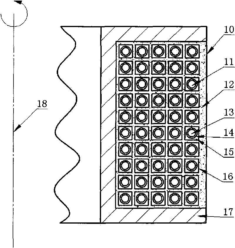
[0021] Such as figure 1 , figure 2 As shown, the fiber optic gyroscope coil 10 of the present invention is formed by winding a continuous prefabricated optical fiber 11 onto the skeleton 17 layer by layer using a quadrupole winding method or other symmetrical winding methods to enhance the reciprocity of the fiber optic gyroscope. The outer surface 16 of the optical fiber is always parallel to the coil axis 18 , and the gap between the optical fibers can be filled with an appropriate packaging material 12 .

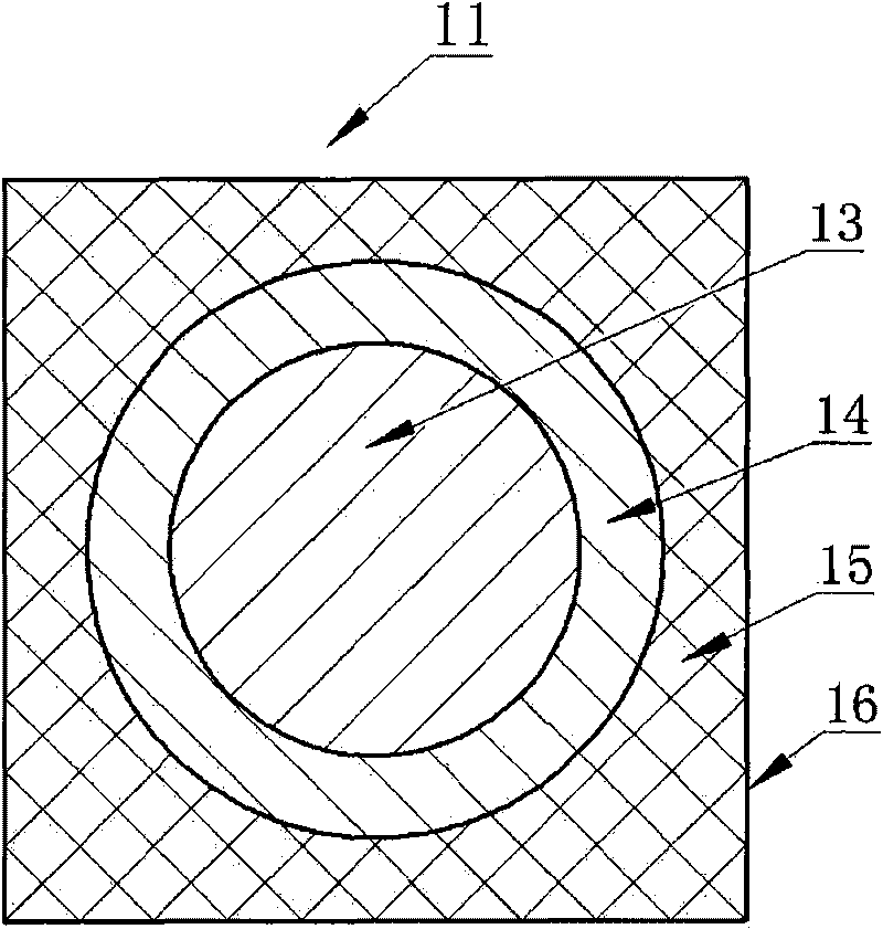
[0022] Such as figure 2 As shown, the prefabricated optical fiber 11 is formed by sequentially coating and curing the buffer layer 14 and the strengthening layer 15 outside the polarization maintaining or ordinary single-mode optical fiber 13; It is composed of a soft material with a very low thermal expansion coefficient and close to the polarization maintaining or ordinary single-mode optical fiber 13. An optional material is silicon rubber; It is composed of a har...


PUM


Abstract

The invention discloses a fiber optic gyro coil wound by square section preformed fibers. The fiber optic gyro coil is formed by winding the square section preformed fibers to a framework layer by layer, and the external surface of one preformed fiber is parallel to the axis of the coil all the time. The square section preformed fiber consists of a buffer layer with circular external section contour line and a reinforced layer with foursquare external section contour line, which are coated and cured outside polarization-preserving or common single-mode fibers in turn. The section of the preformed fibers for winding the coil is foursquare, so the concave phenomenon of the fibers is not easy to happen during winding, and the fiber twist is controlled during winding; the reinforced layer improves the rigidity of the coil, and the buffer layer reduces the stress transfer efficiency to the fibers, so the stress produced by vibration at the fibers is remarkably reduced, and the vibration performance of the coil is improved; and the reinforced layer reduces the thermal expansion degree of the coil, and the buffer layer reduces the thermal stress transfer efficiency to the fibers, so the thermal stress produced by the unmatched thermal expansion at the fibers is remarkably reduced, and the temperature performance of the coil is improved.

Description

technical field [0001] The invention relates to a fiber optic gyro coil, in particular to a fiber optic gyro coil wound with a prefabricated optical fiber with a square cross section. Background technique [0002] The interferometric fiber optic gyroscope is a rotational angular rate sensor based on the Sagnac effect. Its minimum reciprocity structure includes the following parts: a light source, a detector, a fiber directional coupler, and a polarizer (sometimes including one or more depolarizers), an integrated optical Y-waveguide, and a fiber-optic sensing coil wound from polarization-maintaining fiber or ordinary single-mode fiber. The light emitted by the light source passes through the coupler, and is divided by the Y waveguide into light transmitted along the positive and negative directions of the coil. After passing through the coil, the two beams of light are coupled by the Y waveguide and form interference at the receiving end of the detector through the coupler. ...

Claims


Application Information

Patent Timeline
Patent Type & Authority Applications(China)
IPC IPC(8): G01C19/72
Inventor 刘瑞刘承舒晓武
Owner ZHEJIANG UNIV
Learn More