
drying device

A drying device and indoor air technology, which is applied in drying, drying machine, washing device and other directions, can solve the problems of no setting, scattering of foreign objects such as dust, affecting the drying efficiency of the drying device, etc., so as to improve the drying efficiency , The effect of preventing dust from flying around

Inactive Publication Date: 2011-12-14
NANJING LG PANDA APPLIANCES
View PDF1 Cites 1 Cited by
  • Summary
  • Abstract
  • Description
  • Claims
  • Application Information

AI Technical Summary

Problems solved by technology

[0008] However, since there is no special device for forming the air path, the hot air discharged after being guided to the lower part of the dryer will flow to the air guide again and then be sent to the condenser
[0009] In the above case, since the hot air flows into the condenser, the heat exchange efficiency of the condenser will be reduced, thereby affecting the overall drying efficiency of the drying device
[0010] In addition, the discharged hot air will also scatter foreign matter such as dust near the lower part of the dryer to the outside of the dryer.

Method used


Image

  • drying device
  • drying device
  • drying device

Examples


Embodiment Construction

[0026] Hereinafter, a drying device according to an embodiment of the present invention will be described in detail with reference to the accompanying drawings.

[0027] The names of the components used in the description of the present invention are the names given in consideration of the functions played in the present invention. However, the rights of the present invention are not limited to the basic meanings expressed by the names. The names of the constituent parts may be named by other names in the art.

[0028] Hereinafter, a drying device according to an embodiment of the present invention will be described in detail with reference to the accompanying drawings.

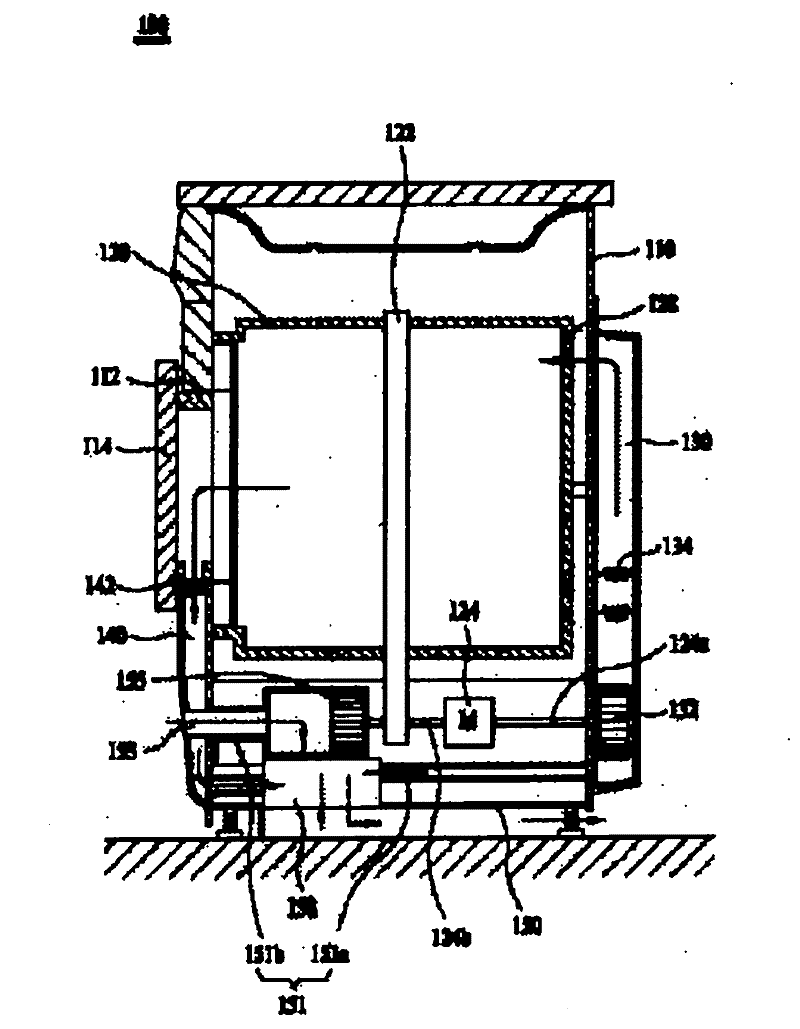
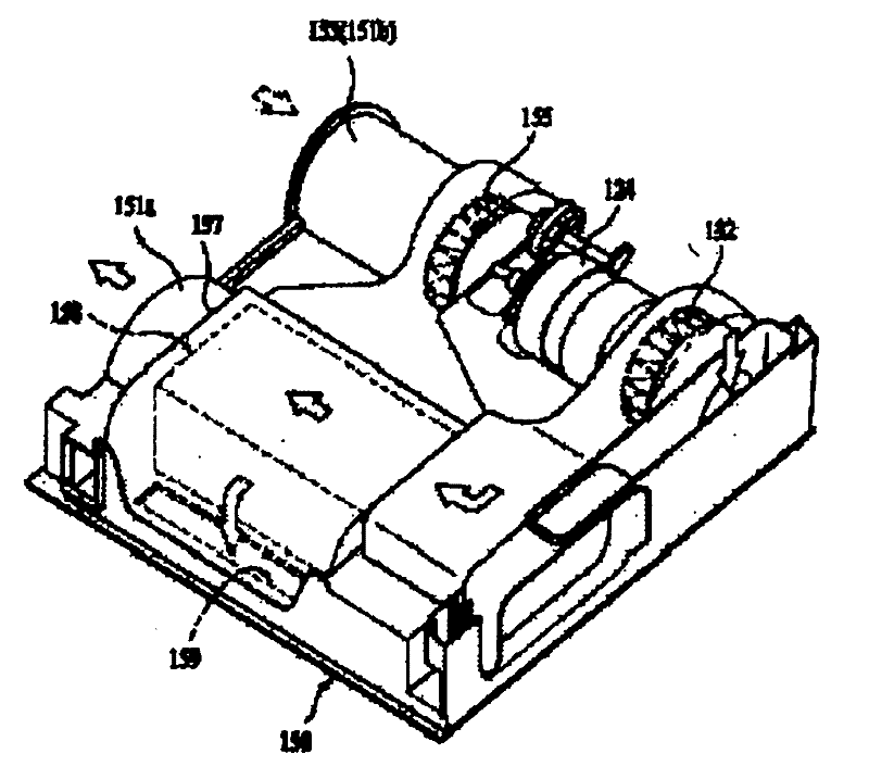
[0029] figure 1 is a schematic diagram showing a drying device according to an embodiment of the present invention. figure 2 It is a perspective view showing the lower structure of a drying device according to an embodiment of the present invention.

[0030] In the drying device 100 , a drum 120 is dispos...


PUM


Abstract

The invention relates to a drying device, which is characterized in that it is composed of the following parts: a shell forming the appearance; a chassis forming the lower part of the shell; a rotatable drum arranged inside the shell; hot air is delivered to the drum The drying air duct; the circulating air duct that circulates the hot air passing through the drum; the condensation flow path that condenses the hot air passing through the drum by using the inhaled indoor air; the above-mentioned The indoor air is discharged to the discharge flow path in the lower part of the above-mentioned chassis. In the drying device of the present invention as described above, since the flow path of the hot air discharged to the lower part of the drying device is formed, it is possible to prevent the reflow of the discharged hot air. In this way, not only can the drying efficiency of the drying device be improved, but also the phenomenon that the discharged hot air can prevent dust from flying around.

Description

technical field [0001] The present invention relates to a drying device, and more specifically relates to improving the discharge path of the hot air generated during the drying process of the drying device discharged to the outside of the drying device, thereby improving the drying efficiency. The invention of the dryer. Background technique [0002] Generally speaking, a drying device is a device for drying laundry, and the above-mentioned drying device can be roughly divided into two types: an exhaust type and a condensation type. Here, the working principle of the exhaust-type drying device can be briefly described as follows, that is, the humid air used for the drying operation is directly discharged to the outside. The working principle of the condensation drying device can be briefly described as follows, that is, after condensing the humid air used for drying operations, the dry air is discharged into the drum again. [0003] The above-mentioned condensing drying d...

Claims


Application Information

Patent Timeline
Patent Type & Authority Patents(China)
IPC IPC(8): D06F58/24D06F58/10D06F58/20
CPCD06F58/24D06F58/26F26B21/002F26B21/003
Inventor 朴秀原李商益金明钟
Owner NANJING LG PANDA APPLIANCES
Learn More