
Automatic cutter relieving mechanism

A driving mechanism and automatic technology, applied in sawing machines, metal sawing equipment, metal processing equipment, etc., can solve the problems of reducing the service life of the saw blade, scratching the cutting section, affecting the cutting quality, etc., to improve the surface accuracy, machining High precision, saving the effect of secondary processing

Inactive Publication Date: 2010-05-12
ZHEJIANG KING MAZON MACHINERY
View PDF1 Cites 19 Cited by
  • Summary
  • Abstract
  • Description
  • Claims
  • Application Information

AI Technical Summary

Problems solved by technology

[0002] After the current cutting machine (or saw) cuts the pipe (or bar, plate), the saw blade is directly lifted up or left behind the material fracture in the case of rotation, so because the saw blade is in the process of rotation It has a swing, so it is easy to scratch and roughen the cutting section during the leaving process, which affects the cutting quality, which is especially important for high-precision and high-demand cutting processing
Moreover, multiple scrapes between the saw blade and the cut material section will also cause wear on the cutting angle of the saw teeth on the saw blade, reducing the service life of the saw blade

Method used


Image

  • Automatic cutter relieving mechanism
  • Automatic cutter relieving mechanism
  • Automatic cutter relieving mechanism

Examples


Embodiment 1

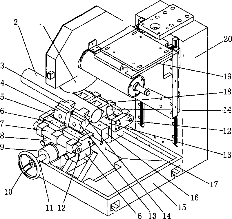
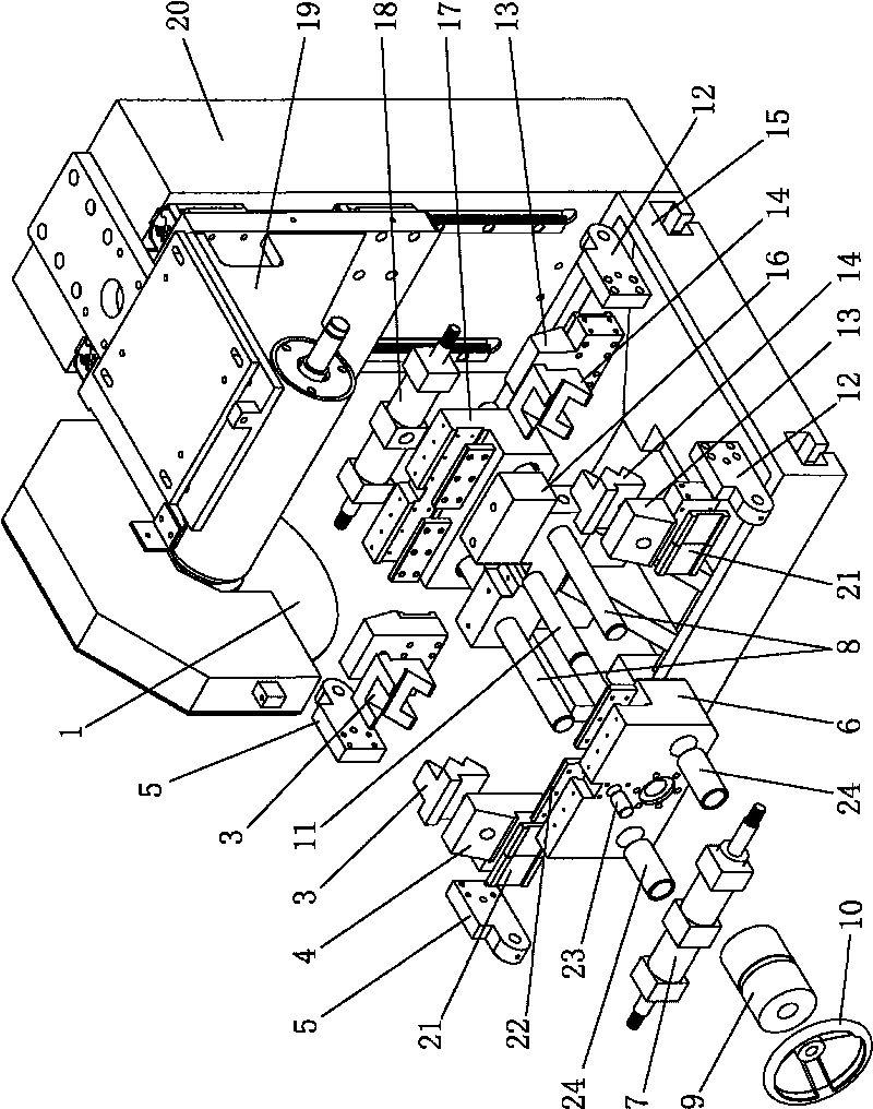
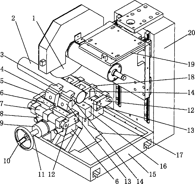
[0016] Such as figure 1 , figure 2 A kind of automatic tool letting mechanism shown, comprises the support 16 that is arranged on the base 15, and a main clamping screw 11 is erected on the support 16, and the axis of the main clamping screw 11 is parallel to the plane of the saw blade 1, and the main clamping screw 11 can rotate but cannot Move along its axial direction; the front main clamp body 6 and the rear main clamp body 17 are sleeved on the main clamp screw rod 11 respectively, the front main clamp body 6 and the main clamp screw rod 11 are empty, and the rear main clamp body 17 and the main clamp screw rod 11 Threaded connection, the front main clip body 6 and the rear main clip body 17 are respectively slidably connected with two main clip optical axes 8 erected on the bracket 16 in parallel with the main clip screw rod 11 through the guide sleeve 24, thus, the front main clip body 6 and the rear main clip body Rear main clip body 17 all can move relative to main ...


PUM


Abstract

The invention discloses an automatic cutter relieving mechanism, which comprises a main clamp screw, a front main clamp body, a rear main clamp body, a clamping cylinder, a left clamp claw and a right clamp claw, wherein a front single claw and a rear single claw of the left clamp claw and the right clamp claw are slidingly connected with the front main clamp body and the rear main clamp body; and the left clamp claw and the right clamp claw are driven to move by driving mechanisms fixed on the front main clamp body and the rear main clamp body. The automatic cutter relieving mechanism comprises the technical scheme that: the driving mechanisms automatically move away two part materials which are cut off leftwards and rightwards, and leave a left gap and a right gap for making a saw blade lift or transverse and the like to retreat from a material position so as to avoid the saw blade contacting the materials and scratching (or galling) the fracture surfaces of the materials in the process of leaving the materials, to improve surface accuracy of a cut-off surface, to omit secondary machining of the fracture surfaces of the cut-off materials, and to improve the service life of the saw blade. The automatic cutter relieving mechanism has the advantages of reasonable structure, high machining accuracy, good stability, reliable operation, convenient adjustment and the like.

Description

technical field [0001] The invention belongs to the technical field of cutting processing, and in particular relates to an automatic knife-releasing mechanism used on a cutting machine (or saw). Background technique [0002] After the current cutting machine (or saw) cuts the pipe (or bar, plate), the saw blade is directly lifted up or left behind the material fracture in the case of rotation, so because the saw blade is in the process of rotation With a swing, it is easy to scratch and roughen the cutting section during the leaving process, which affects the cutting quality, which is especially important for high-precision and high-demand cutting processing. Moreover, multiple scrapes between the saw blade and the section of the cutting material will also cause wear on the cutting angle of the sawtooth on the saw blade, reducing the service life of the saw blade. Contents of the invention [0003] In order to solve the above-mentioned technical problems, the object of th...

Claims


Application Information

Patent Timeline
Patent Type & Authority Applications(China)
IPC IPC(8): B23D47/10
Inventor 林伟明陈朝阳陈金才施李杰
Owner ZHEJIANG KING MAZON MACHINERY
Learn More