Ceramic filled type neutron tube

A filling type and neutron tube technology, applied in the field of neutron tubes, can solve the problems of difficult processing and low yield, and achieve the effects of reducing discharge, increasing output, and ensuring collimation

Inactive Publication Date: 2010-04-28
NORTHEAST NORMAL UNIVERSITY
View PDF0 Cites 3 Cited by
  • Summary
  • Abstract
  • Description
  • Claims
  • Application Information

AI Technical Summary

Problems solved by technology

[0003] In order to overcome the difficulty of processing the existing neutron tubes and the shortcomings of low yield, the present invention provides an improved neutron tube. The collimated mold avoids the eccentricity and distortion caused by the deformation of the mold, and effectively improves the output, life and stability of the neutron tube

Method used


Image

  • Ceramic filled type neutron tube
  • Ceramic filled type neutron tube

Examples


Embodiment Construction

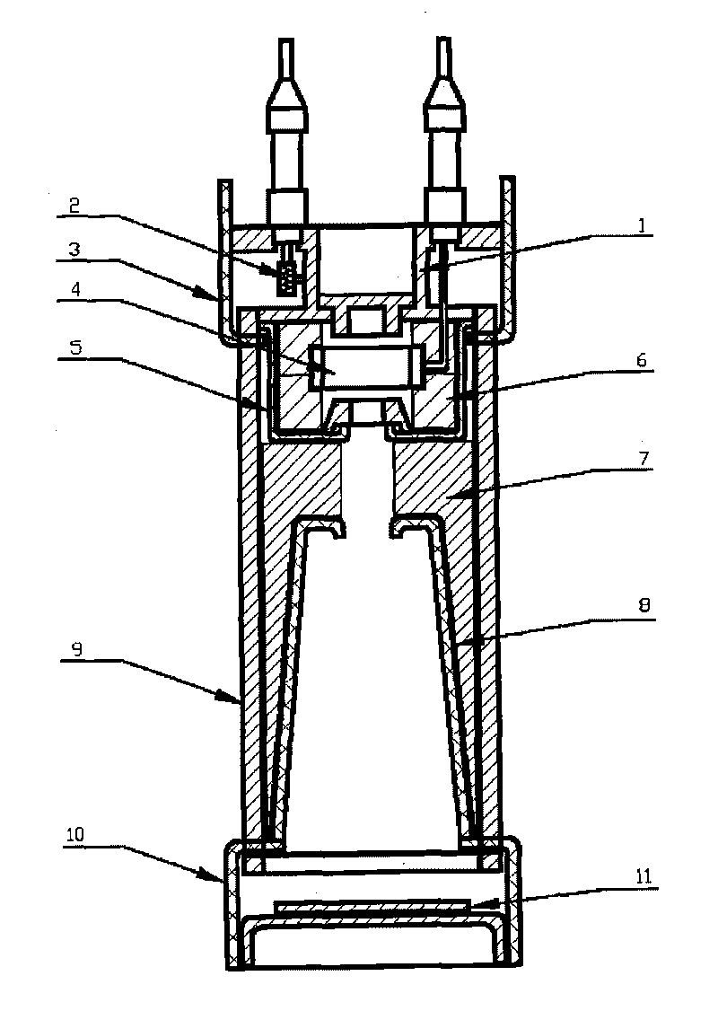
[0008] The neutron tube of the present invention is a circular axisymmetric structure, which seals the ion source, acceleration system, target and air pressure adjustment system in a ceramic tube to form an electric vacuum device with a simple and compact structure and easy use. The relationship with the location is shown in the attached figure. First, the copper head 1 and the target 11 are prepared and cleaned; then the upper cover 3, the ion source cover 5, the ceramic insulating ring 7, the acceleration cylinder 8, the lower cover 10 and the ceramic shell 9 are sealed together, and the ion source cover 5 and the ceramic insulating ring 7 placed between the acceleration cylinder 8, the inner side should ensure close contact with the ion source cover 5 and the acceleration cylinder 8, and the outer diameter is the same as the inner diameter of the ceramic shell 9. Between the ion source cover 5 and the acceleration cylinder 8 There is a center hole between them, the diameter...


PUM


Abstract

The invention belongs to an improved turn-off neutron source, and in particular relates to a neutron tube. In the neutron tube, a ceramic insulating ring is filled between an anode cylinder and an ion source cover and another ceramic insulating ring is filled between the ion source cover and an accelerating cylinder, so an air-out space in the neutron tube is reduced, insulating strength is improved, sealing difficulty is reduced and the coaxiality of a system is effectively guaranteed. The neutron tube has the advantages of greatly reducing discharging and puncturing probabilities, guaranteeing the collimation of the neutron tube, improving the product yield, service life and stability of the neutron tube and realizing the industrialization of the machining and manufacturing of the neutron tube, wherein phi50 is taken as an example, the service life of an improved product is increased by more than 3 times, while the product yield is increased by about 5 times, the stability is not more than 3 percent and the finished product ratio is over 90%.

Description

technical field [0001] The invention belongs to an improved shut-off neutron source, in particular to a neutron tube. Background technique [0002] At present, the known ceramic self-targeting neutron tube is composed of a copper head, a storage tank, an upper mask, an anode cylinder, an ion source cover, a ceramic shell, an accelerating cylinder, a lower mask, and a target. After applying a voltage of several thousand volts to the anode cylinder, turn on the low-voltage power supply of the storage, heat the storage, release the deuterium-tritium mixed gas in the storage, ionize into deuterium-tritium ions in the ion source, and then add The negative high voltage of tens of thousands of volts to hundreds of thousands of volts draws out deuterium-tritium ions and accelerates the bombardment to the target, generating 14 Mev neutrons. However, during the manufacture of neutron tubes, it is easy to discharge between the ion source cover and the acceleration tube, and between th...

Claims


Application Information

Patent Timeline
Patent Type & Authority Applications(China)
IPC IPC(8): H01J27/00G21G4/02
Inventor 乔双严长春景士伟
Owner NORTHEAST NORMAL UNIVERSITY
Why Eureka
Try Eureka