
Software radio-based wireless communication customer premises equipment

A technology of user end equipment and software radio, which is applied in wireless communication, telephone communication, branch office equipment, etc., can solve the problems of difficult upgrading of hardware products, unusable user end equipment, and single function, so as to save hardware cost, Improve user communication quality and save system resources

Active Publication Date: 2010-04-21
赵明 +1
View PDF7 Cites 18 Cited by
  • Summary
  • Abstract
  • Description
  • Claims
  • Application Information

AI Technical Summary

Problems solved by technology

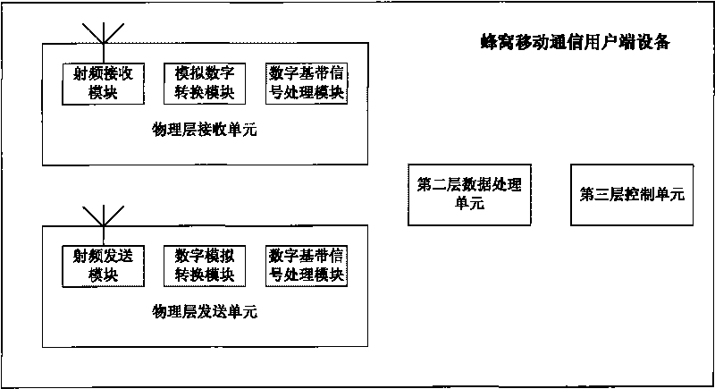
[0020] 1) Single function: In order to keep down the cost, the dedicated chip only has a relatively single function and cannot be compatible with other systems
For example, the baseband signal processing chip of GSM cannot complete the baseband signal processing function of WCDMA
[0021] 2) Difficulty in upgrading: It is difficult to upgrade hardware products. With the upgrading of communication systems and communication protocols, the hardware of client devices needs to be replaced accordingly. Old client devices cannot continue to be used in the new system
[0022] 3) High development cost: the development process of dedicated chips and hardware circuits is complicated, especially the development of chips requires tape-out, manufacturing and other processes, and the cost is difficult to reduce
However, CN101014103 does not take into account the needs of different wireless communication client devices, cannot provide the transmitting function of wireless communication client devices, and does not consider realizing different types of wireless communication client devices under a unified structure

Method used


Image

  • Software radio-based wireless communication customer premises equipment
  • Software radio-based wireless communication customer premises equipment
  • Software radio-based wireless communication customer premises equipment

Examples


Embodiment Construction

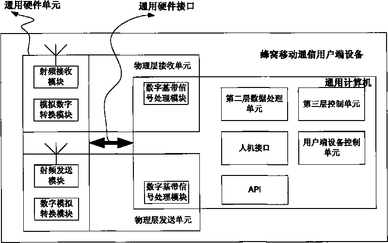
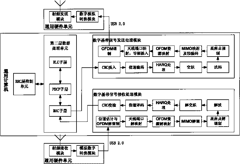
[0041] figure 2 An example of wireless communication user terminal equipment based on the present invention is given. As shown in the figure, the general-purpose computer implements the digital baseband signal receiving and processing module of the physical layer unit of the user terminal equipment, the digital baseband signal sending and processing module of the physical layer unit, the second layer data processing unit, the third layer control unit, and the man-machine interface unit, a client device control unit, and an application programming interface (API). The digital baseband signal receiving and processing module demodulates and decodes the received digital signal; the digital baseband signal sending and processing module encodes and modulates the physical layer data signal; the second layer data processing unit is used for packing and unpacking data packets , data retransmission, data encryption and decryption, etc.; the third layer control unit, used to control th...


PUM


Abstract

The invention discloses software radio-based wireless communication customer premises equipment, which at least comprises a general purpose hardware unit, a general purpose computer and a general purpose hardware interface. The general purpose hardware unit realizes the radio frequency transmission and reception, analogue-to-digital conversion and the digital-to-analogue conversion of a physical layer unit of the customer premises equipment. The general purpose computer implements the digital baseband signal transmission and reception processing, layer two data processing and layer three data control of the physical layer unit of the customer premises equipment and controls and allocates the general purpose hardware unit. The general purpose hardware interface is connected with the computer and the general purpose hardware unit, realizes the interactive transmission of the digital baseband signal and other control signals between the computer and the general purpose hardware unit. The invention provides general purpose wireless communication customer premises equipment based on the basic ideal of software radio. The equipment can select available wireless communication service flexibly according to requirements of users and a local environment and implements corresponding wireless communication function.

Description

technical field [0001] The invention belongs to the technical field of wireless communication, and in particular relates to a wireless communication user end device based on software radio. Background technique [0002] Wireless communication client equipment can be divided into the following categories according to the type of communication system and the purpose of the client equipment: [0003] 1) Cellular System client equipment, especially client equipment that implements one or more of the following mobile communication protocols, including GSM / GPRS / EDGE, IS-95, WCDMA / HSDPA / HSUPA, CDMA2000 / CDMA2000EV-DO, TD-SCDMA, 3GPP LTE, etc.: [0004] a) Client equipment that supports voice and data services at the same time: a mobile phone that supports at least one cellular mobile communication protocol [0005] b) User terminal equipment that only supports data services to enable personal computers to access the Internet anytime and anywhere: a data card that supports at leas...

Claims


Application Information

Patent Timeline
Patent Type & Authority Applications(China)
IPC IPC(8): H04W80/00H04W88/02H04M1/725H04M1/72409
Inventor 赵明齐心张虎
Owner 赵明
Learn More