Phase type photon sieve

A photon sieve and phase-type technology, applied in the direction of diffraction grating, etc., can solve the problems of low diffraction efficiency, weakening the focus, and affecting practicality, etc., and achieve the effects of excellent diffraction efficiency, improved resolution, and improved competitiveness

Inactive Publication Date: 2010-04-14
INST OF OPTICS & ELECTRONICS - CHINESE ACAD OF SCI
View PDF0 Cites 13 Cited by
  • Summary
  • Abstract
  • Description
  • Claims
  • Application Information

AI Technical Summary

Problems solved by technology

However, since only the small holes distributed in the light-transmitting ring zone contribute to the formation of the focus, while other regions will weaken the forma

Method used


Image

  • Phase type photon sieve
  • Phase type photon sieve
  • Phase type photon sieve

Examples


Embodiment Construction

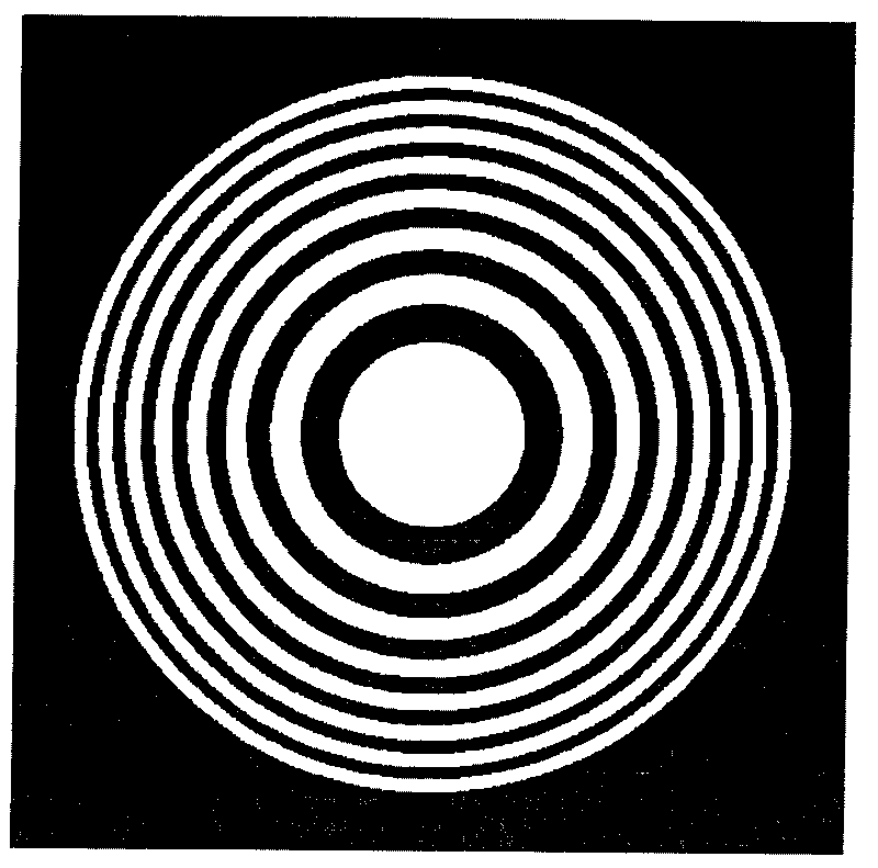
[0020] Such as figure 1 Shown is a schematic diagram of the structure of a Fresnel zone plate. In this specific embodiment, the wavelength of the incident light source is 355 nm, the diameter of the zone plate is 1 mm, and the focal length is 10 mm. Record N as the number of bands, then N=D 2 / λ×f=281; record r n is the radius of each ring, then f is the focal length, λ is the wavelength, n is the serial number of the zone plate, N is the total number of zones of the zone plate, and the value range of n is less than or equal to N; the diagram only shows the first 16 zones, and so on . The radii of the first 16 rings are r 1 ...r 16 = 60.42μm, 85.44μm, 104.64μm, 120.83μm, 135.09μm, 147.99μm, 159.84μm, 170.88μm, 181.25μm, 191.05μm, 200.37μm, 209.28μm, 217.83μm, 223.062μm, 26.032μm, 26 The difference between the radii of two adjacent rings is the width of the ring, which is denoted as w n , then the width of the annulus is 25.02 μm, 19.20 μm, 16.19 μm, 14.16 μm, 12.90 μm...


PUM


Abstract

A phase type photon sieve is improved from a conventional Fresnel zone plate structure and consists of orifices distributed on transparent and non-transparent annulus of the Fresnel zone plate randomly, wherein Pi-phase shift is existed between the orifices on the transparent annulus and the orifices on the non-transparent annuls, and phase difference is achieved by accurately controlling etching depth of each annulus. Manufacturing process of the phase type photon sieve is completed by an electro beam machining process. Compared with the Fresnel zone plate, the phase type photon sieve can keep high diffraction efficiency and simultaneously has more excellent resolution capacity. Compared with an amplitude photon sieve, the phase type photo sieve can keep high resolution capacity and simultaneously has more excellent diffraction efficiency. As an excellent nano-level diffraction imaging device, the phase type photon sieve can be widely applied to fields of photo-etching, astronomical observation, air shot, weapon vision and the like.

Description

technical field [0001] The invention is a phase photon sieve, which belongs to the field of diffractive optical devices or micro-optical elements. Background technique [0002] Today, optical imaging systems are rapidly developing toward ultra-light, ultra-small, and super-resolution in many special and important occasions. Conventional refractive optical systems are gradually being replaced by refractive-diffractive hybrid optical systems or even purely diffractive optical systems. Diffractive optical elements are widely used in optical sensing, optical communication, optical It has broad application prospects in computing, optical storage, laser medicine, microlithography, astronomical observation and other fields. Binary optical element is a new type of diffractive optical element that has been developed rapidly in recent years. Its typical representative is Fresnel zone plate, which is not only similar to ordinary lenses in terms of light collection, but also similar to...

Claims


Application Information

Patent Timeline
IPC IPC(8): G02B5/18
Inventor 蒋文波胡松赵立新徐锋邢嶶杨勇严伟
Owner INST OF OPTICS & ELECTRONICS - CHINESE ACAD OF SCI
Why Eureka
Try Eureka