
Reactor

一种电抗器、散热底座的技术,应用在电感器、固定电感器、电路等方向,能够解决振动未被有效抑制等问题,达到高振动衰减性能、高散热性能的效果

Inactive Publication Date: 2010-03-31
TOYOTA JIDOSHA KK
View PDF1 Cites 27 Cited by
  • Summary
  • Abstract
  • Description
  • Claims
  • Application Information

AI Technical Summary

Problems solved by technology

However, also in this reactor device, the vibration caused when the reactor device operates is not effectively suppressed, like other reactor devices in the prior art
Furthermore, it is difficult to improve the manufacturing yield of the reactor device by simplifying the process for manufacturing the reactor device

Method used


Image

  • Reactor
  • Reactor
  • Reactor

Examples


Embodiment Construction

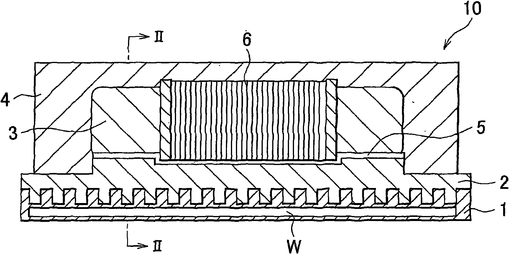
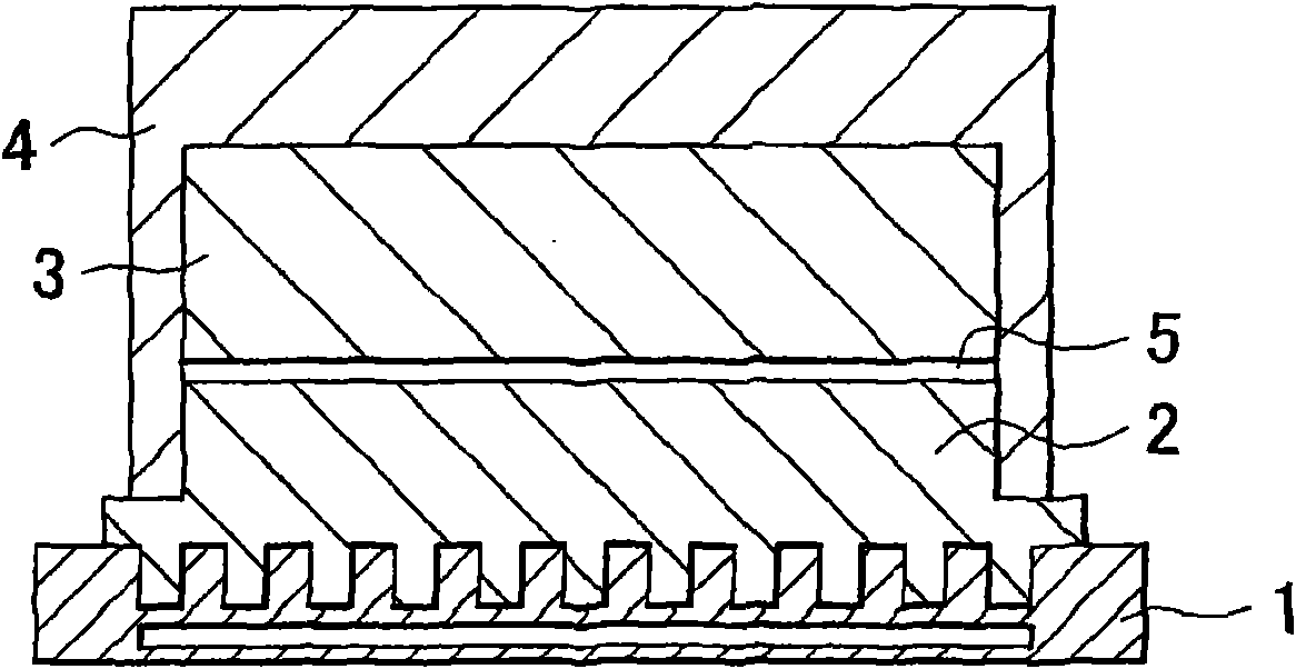
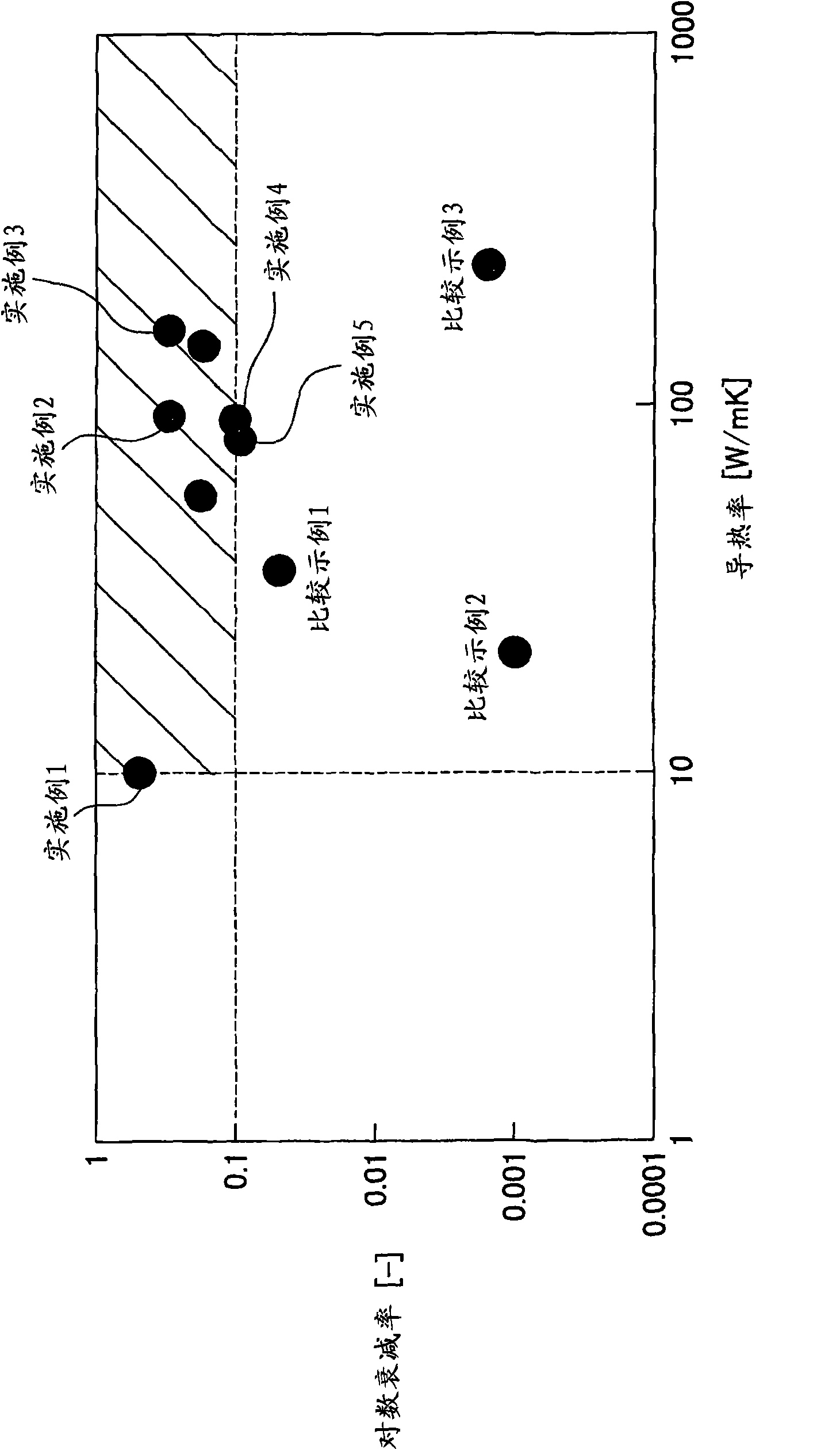
[0025] Hereinafter, one embodiment of the present invention will be described with reference to the accompanying drawings. figure 1 is a longitudinal sectional view showing a reactor according to an embodiment of the present invention. figure 2 is along figure 1 A cross-sectional view taken along the line II-II. image 3 is a graph showing test results related to the logarithmic decay rate and thermal conductivity of metals / alloys. Figure 4 It is a figure which schematically shows the experiment concerning the vibration of a reactor. Figure 5 to Figure 7 Graphs showing measurement results of vibrations in the X direction, vibrations in the Y direction, and vibrations in the Z direction in the vibration experiment, respectively. Figure 8 It is a graph showing the measurement result of the temperature of the upper part of the coil.

[0026] figure 1 is a longitudinal sectional view showing a reactor 10 according to an embodiment of the present invention and figure 2 i...


PUM


Abstract

A reactor includes a cooling block; a heat radiation base affixed to the cooling block; a reactor core that includes a coil, and that is affixed to the heat radiation base; and a resin molded body formed on the heat radiation base to cover the reactor core. The heat radiation base is formed of a metal or an alloy that has a predetermined logarithmic decrement and predetermined heat conductivity. The predetermined logarithmic decrement is equal to or higher than 0.1, and the predetermined heat conductivity is equal to or higher than 10 W / mK.

Description

technical field [0001] The present invention relates to a reactor provided in an electric vehicle, a hybrid vehicle, and the like. Background technique [0002] Generally, a reactor core is provided in a reactor in a power conversion circuit, the reactor core has a substantially long ring shape in plan view, and a coil is formed around each of two longitudinal portions of the reactor core. The reactor in this state is housed in the case. Reactor cores include partial cores. Each partial core is formed of a laminated body formed of a plurality of electromagnetic steel sheets or is formed of a powder magnetic core. Gap plates formed of non-magnetic material are disposed between the partial cores. The interstitial plates are secured to the local core by adhesive. Therefore, a reactor is formed. [0003] The heat sink is provided on the lower surface (bottom surface) of the case. Furthermore, a cooling block is arranged below the housing. Coolant or air is supplied into t...

Claims


Application Information

Patent Timeline
Patent Type & Authority Applications(China)
IPC IPC(8): H01F27/22
CPCH01F27/022H01F27/266H01F27/22H01F37/00H01F27/025
Inventor 佐藤丰幸
Owner TOYOTA JIDOSHA KK
Learn More