Valve combination for regulating the flow rate or differential pressure

A valve group and differential pressure technology, used in flow control, auxiliary non-electrical flow control, control/regulation systems, etc. The effect of simplified installation

Active Publication Date: 2010-03-31
F W OVENTROP KG
View PDF3 Cites 14 Cited by
  • Summary
  • Abstract
  • Description
  • Claims
  • Application Information

AI Technical Summary

Problems solved by technology

The corresponding components are therefore difficult to reach and see for adjustment and data reading

Method used


Image

  • Valve combination for regulating the flow rate or differential pressure
  • Valve combination for regulating the flow rate or differential pressure
  • Valve combination for regulating the flow rate or differential pressure

Examples


Embodiment Construction

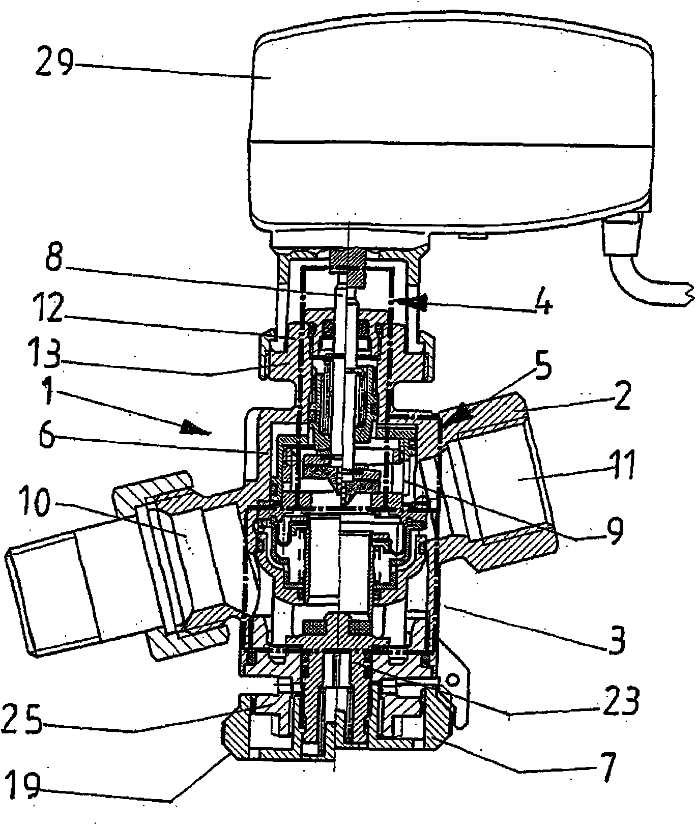
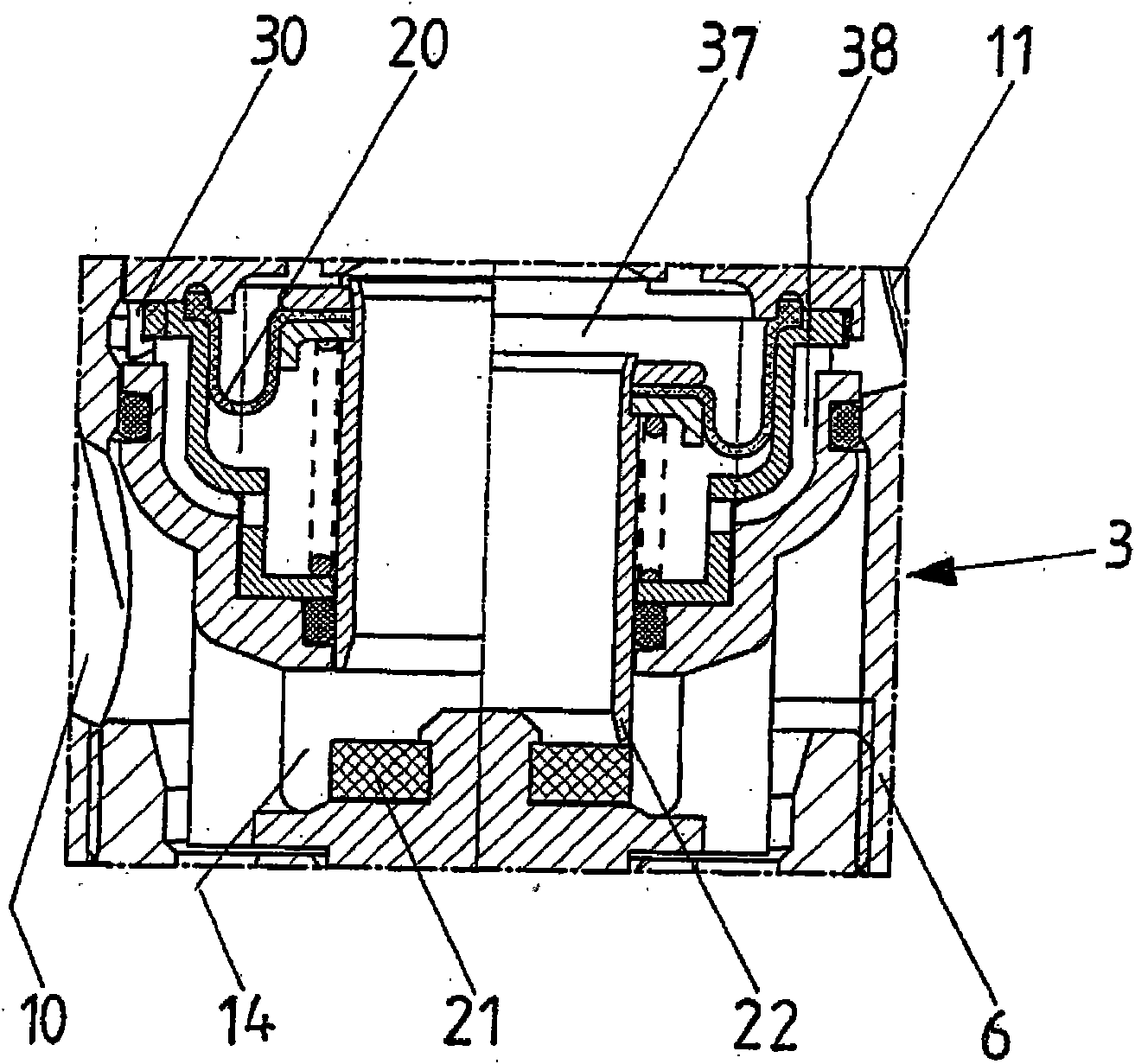
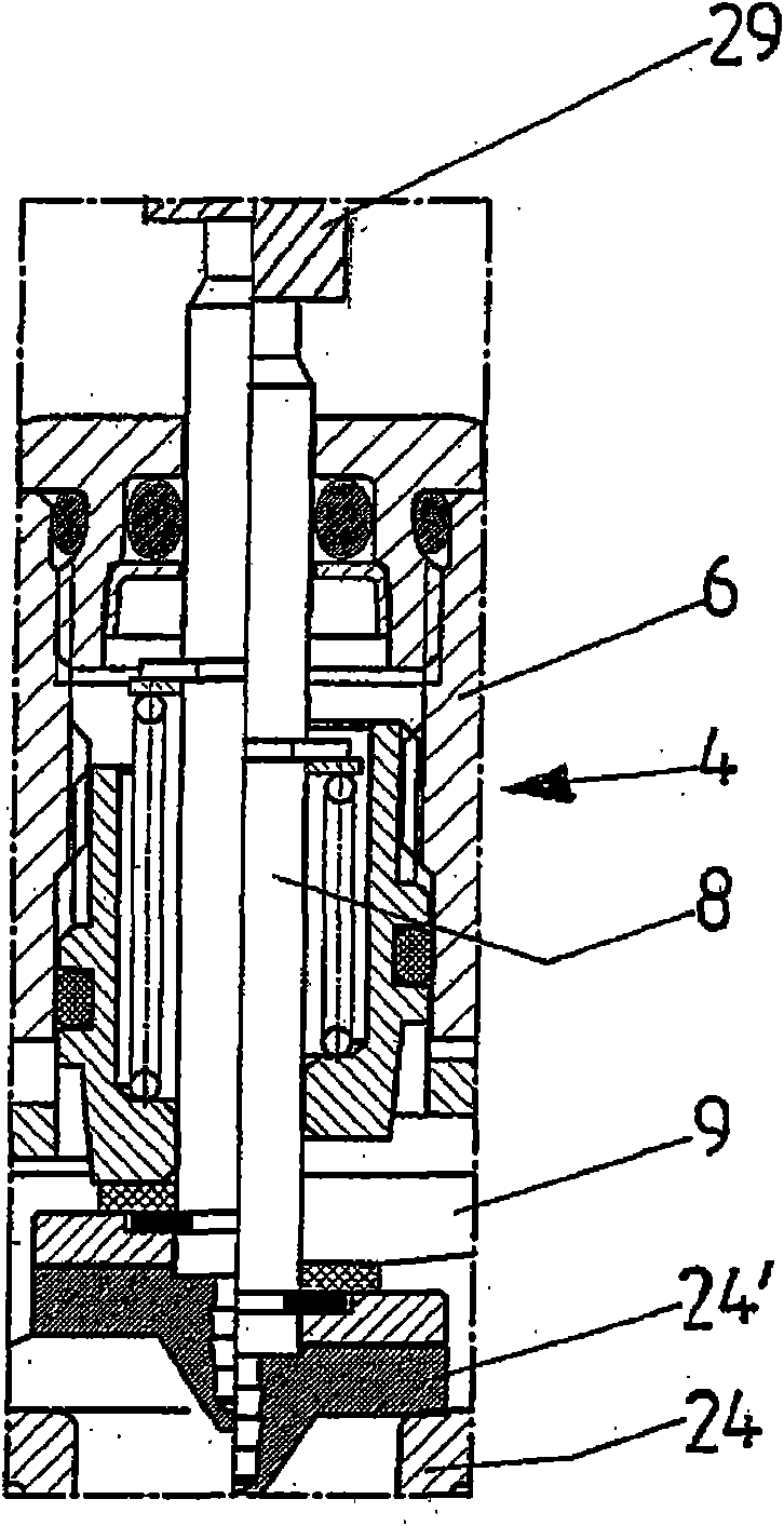
[0057] The figures show a valve block 1 for regulating a flow or a differential pressure in a fluid-carrying heating or cooling installation. It consists of a housing 2 with an inlet connection 10 , an outlet connection 11 and a connecting pipe 6 arranged between them. Arranged axially in the connecting pipe 6 is an adjustment device 3 which is equipped with a movable partition 20 for the rated load. The diaphragm 20 controls the differential pressure by means of a closure element 22 acting on the first support 21 to change the adjustment cross-section 14 , wherein the adjustment device 3 can be adjusted by means of a first flow adjustment also arranged axially in the connecting pipe 6 . The device 4 keeps the pressure difference constant at a predetermined value by means of a presettable second flow regulating device 5 arranged axially or coaxially with the first flow regulating device 4, wherein the first flow regulating device 4 It is adjustable via the actuating element 8...


PUM


Abstract

The invention relates to a valve combination (1) for regulating the flow rate or differential pressure in liquid-carrying heating or cooling systems, comprising a housing (2) which is provided with afeed pipe (10), a discharge pipe (11) and a connection pipe (6) arranged therebetween, and a regulating device (3) which is arranged axially in the connection pipe (6), wherein the regulating device (3) keeps the differential pressure constant at a predefined value by means of a first flow regulating device (4), which is likewise arranged axially in the connection pipe (6) and can be adjusted by an actuating part (8) which projects from the housing (2) and acts on a second seat (24), and by means of a second flow regulating device (5) which is arranged axially or coaxially with respect to thefirst flow regulating device and can be preset, wherein the flow cross section (9) can be set, which is characterized in that, when an actuator (29) which acts on the actuating part (8) is installed,the flow cross section (9) can be adjusted by means of a handle (7) which is not concealed by the actuator, and in that, when the actuator (29) is installed, the position of the handle (7) can be readon a display device (19) which is not concealed by the actuator, and the display device (19) depicts the presetting of the flow cross section (9).

Description

technical field [0001] The invention relates to a valve group for adjusting flow rate or differential pressure in heating equipment or cooling equipment guiding fluid, which consists of a valve block provided with an inlet pipe connection, an outlet pipe connection and a connecting pipe between the two One-piece or combined housing and an adjustment device arranged axially in the connecting pipe, the adjustment device is equipped with a movable diaphragm loaded with a rated value, and the diaphragm controls the pressure difference by acting on the first support The adjustment cross-section can be changed by means of a closing part of the connecting pipe, wherein the adjustment device is arranged axially or coaxially with the first flow adjustment device by means of a first flow adjustment device arranged axially or coaxially with the first flow adjustment device. Two flow regulating devices maintain the pressure difference at a predetermined value, wherein the flow cross-secti...

Claims


Application Information

Patent Timeline
Patent Type & Authority Applications(China)
IPC IPC(8): G05D7/00
CPCG05D7/005Y10T137/7722Y10T137/7784Y10T137/7791Y10T137/7808Y10T137/8225
Inventor G·洛夫勒
Owner F W OVENTROP KG
Why Eureka
Try Eureka